 |
VOOZH | about |
|
VOOZH | about |
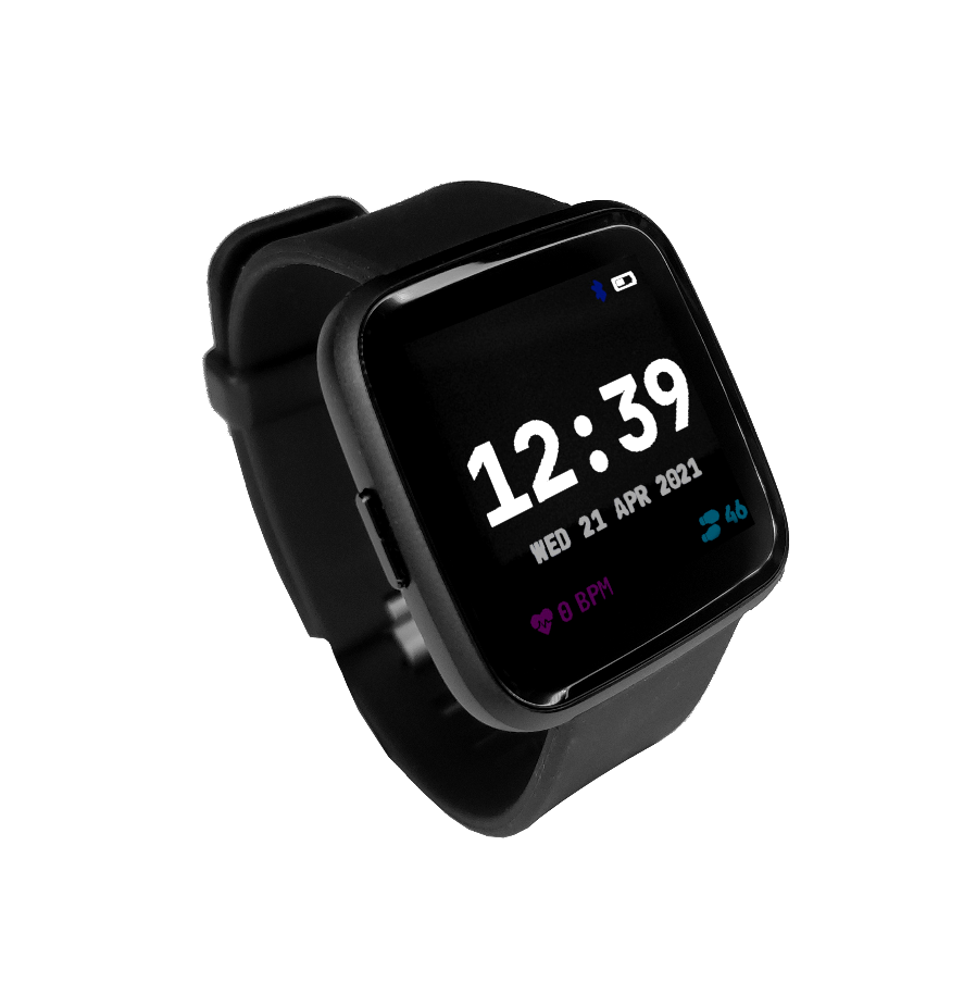
The PineTime is a free and open source smartwatch capable of running custom-built open operating systems. Some of the notable features include a heart rate monitor, a week-long battery, and a capacitive touch IPS display that is legible in direct sunlight. It is a fully community driven side-project which anyone can contribute to, allowing you to keep control of your device.
Read these first!
The frequently asked question can be found in the article PineTime FAQ.
The current default operating system on the PineTime is called InfiniTime, you can find more information about the firmware on its GitHub page. First devkits shipped with a proprietary custom firmware.
You can find a list of available firmware and other software here: PineTime Development
PineTime/InfiniTime needs a companion app to e.g. upload a firmware, get notifications from a phone, or just get the date/time. Here are some companion apps:
Developers and coding:
To read more about development on the PineTime, the projects available and more technical details, check out PineTime Development
If you want to dive in to the ecosystem, here's a short list of various articles and blog posts that can help you set up your soft- or hardware development environment.
Note: The factory-default software on the PineTime does not auto-detect the display being disconnected when it has already booted. That can cause garbled output, to fix it just restart the PineTime.
The display is driven using the ST7789 display controller. Use the following pins to drive the screen:
| PineTime pin | ST7789 pin |
|---|---|
| LCD_SCK (P0.02) | SPI clock |
| LCD_SDI (P0.03) | SPI MOSI |
| LCD_RS (P0.18) | Command/Data pin (CD) |
| LCD_CS (P0.25) | Chip select |
| LCD_RESET (P0.26) | Display reset |
| LCD_BACKLIGHT_{LOW,MID,HIGH} | Backlight (active low) |
Notes:
References:
Reading whether the PineTime has power attached is easy: simply read the charge indication pin (P0.12). When it is high it is running on battery, when it is low it is charging.
Reading the battery voltage is a bit harder. For that you can use the battery voltage pin on P0.31 (AIN7). The returned value is 12 bits, which means it is 0..4095. You can get the measured voltage with the following formula, assuming a reference voltage of 3.3V (this is configurable in the ADC):
adcVoltage = adcValue / (4095 / 3.3)
The measured voltage is actually half of the actual battery voltage, because the ADC is connected between a voltage divider where both resistors are 1MΩ. This can be corrected by multiplying the value:
batteryVoltage = adcValue * 2 / (4095 / 3.3)
It's often better to avoid floating point values on embedded systems and in this case there is no reason to use float at all, we can just represent the value in millivolts. Therefore the formula can be simplified to:
batteryVoltage = adcValue * 2000 / (4095 / 3.3)
batteryVoltage = adcValue * 2000 / 1241
Converting this voltage to an estimated capacity in percent requires a more complicated algorithm, because Lithium-ion batteries have a non-linear discharge curve.
The button on the side of the PineTime is disabled by default. To enable it, drive the button out pin (P0.15) high.
While enabled, the button in pin (P0.13) will be high when the button is pressed, and low when it is not pressed.
Note that the button consumes around 34µA when P0.15 is left high. To reduce current consumption, set it to low most of the time and only set it to high shortly before reading it. The button needs a short time to give good outputs though, setting P0.15 high at least four times in a row seems to result in enough delay that P0.13 has a stable output.
The touch panel is controlled by a Hynitron CST816S chips. Unfortunately, there is not much information about this chip on the internet apart from the datasheet below and a reference driver. This is enough to implement a basic driver, but crucial information needed to implement advanced functionalities are missing (I²C protocol and registers, timings, power modes,...).
NOTE: The controller goes to sleep when no event is detected. In sleep mode, the controller does not communicate on the I²C bus (it appears disconnected). So, for the communication to work, you need to tap on the screen so that the chip wakes-up.
NOTE: The I²C bus, also known as TWI bus, has known issues, make sure to write your TWI driver with timeouts.
Touch information is available from the 63 first registers of the controller. Remember: the device is in sleep mode when no touch event is detected. It means that you can read the register only when the touch controller detected an event. You can use the Interrupt pin to detect such event in the software.
These 63 bytes contain up to 10 touch point (X, Y, event type, pressure,...) :
| Byte | Bit7 | Bit6 | Bit5 | Bit4 | Bit3 | Bit2 | Bit1 | Bit0 |
|---|---|---|---|---|---|---|---|---|
| 0 | ? | |||||||
| 1 | GestureID : (Gesture code ,
0x00: no gesture, 0x01: Slide down, 0x02: Slide up, 0x03: Slide left, 0x04: Slide right, 0x05: Single click, 0x0B: Double click, 0x0C: Long press) | |||||||
| 2 | ? | Number of touch points | ||||||
| 3 | Event (0 = Down, 1 = Up, 2 = Contact) | ? | X (MSB) coordinate | |||||
| 4 | X (LSB) coordinate | |||||||
| 5 | ? | Touch ID | Y (MSB) coordinate | |||||
| 6 | Y (LSB) coordinate | |||||||
| 7 | Pressure (?) | |||||||
| 8 | Miscellaneous (?) | |||||||
Bytes 3 to 8 are repeated 10 times (10*6 + 3 = 63 bytes).
NOTES
The reference driver specifies some registers and value, but there is no information about them:
| Register | Address | Description |
|---|---|---|
| HYN_REG_INT_CNT | 0x8F | |
| HYN_REG_FLOW_WORK_CNT | 0x91 | |
| HYN_REG_WORKMODE | 0x00 | 0 = WORK, 0x40 = FACTORY |
| HYN_REG_CHIP_ID | 0xA3 | |
| HYN_REG_CHIP_ID2 | 0x9F | |
| HYN_REG_POWER_MODE | 0xA5 | 0x03 = SLEEP (reset the touchpanel using the reset pin before using this register : pin_low, delay 5ms, pin_high, delay 50ms then write 3 to register 0xA5) |
| HYN_REG_FW_VER | 0xA6 | |
| HYN_REG_VENDOR_ID | 0xA8 | |
| HYN_REG_LCD_BUSY_NUM | 0xAB | |
| HYN_REG_FACE_DEC_MODE_EN | 0xB0 | |
| HYN_REG_GLOVE_MODE_EN | 0xC0 | |
| HYN_REG_COVER_MODE_EN | 0xC1 | |
| HYN_REG_CHARGER_MODE_EN | 0x8B | |
| HYN_REG_GESTURE_EN | 0xD0 | |
| HYN_REG_GESTURE_OUTPUT_ADDRESS | 0xD3 | |
| HYN_REG_ESD_SATURATE 0xED | 0xED |
WARNING :
The on board accelerometer in devices shipped before July 2021 is a Bosch BMA421, connected to the I2C bus. Devices shipped after July 2021 use a Bosch BMA425 accelerometer.
I2C Device address : 0x18
The PineTime appears to be able to sleep with a current consumption of only 66µA.
To investigate current consumption, it's a good idea to disable everything possible to get the lowest current consumption possible, and then re-enable things one by one. Here is one way to get a baseline current consumption of 60µA, as measured from the 3.3V pin with the battery disconnected:
sd_app_evt_wait instead).Here are some current consumption statistics (current consumed in addition to the baseline power), roughly ordered from large to small:
| Source | Current | Notes |
|---|---|---|
| SWD | 3.05mA | Power cycle the chip after programming to avoid this, it can hide other inefficiencies. |
| LCD | 5.61mA | Set the LCD to sleep mode when not used, using SLPIN. |
| Backlight high | 12.27mA | |
| Backlight mid | 5.51mA | |
| Backlight low | 1.83mA | |
| ADC left enabled | 1.3mA | Stopping SAADC brings the current back to the baseline. It seems that it doesn't need to be disabled entirely. |
| UART left enabled | 1.25mA | Some bootloaders might leave the UART enabled after they start the application, leading to high current consumption. |
| Edge triggered pin interrupts | 0-0.47mA? | It appears that under some configurations, edge triggered interrupts result in a large power drain. One way to avoid this is by using the pin sense mechanism. |
| Accelerometer | 0.15mA | 151µA in performance mode, 99µA with performance mode disabled but power saving disabled, 50µA while polling on a high interval (100Hz, average 4 samples), 14µA when running at the lowest possible setting that still counts steps (50Hz, no averaging). |
| HRS sensor is enabled | 0.1mA | The HRS3300 sensor is enabled on power on. Write byte 0x00 to the PDRIVER register (0x0C) to set it in sleep mode. |
| BUTTON_OUT left high | 0.04mA | See Button for how to avoid this. |
| SPI flash sleep mode | 0.014mA | Sleep mode still consumes power. Put it in deep power down mode to avoid this. |
| SPI, I2C | (negligible) | SPI and I2C appear to consume very little power when idle, around 1µA or less. |
The following accessory is compatible with the PineTime.
The PineTime uses a standard 20mm watch band / strap. There is a thread in the forum discussing this.
Due to the watches design. Retention for the spring bars are recessed into the watch. Not all 20mm bands / straps work. This is especially the case for Nato style bands / straps being too thick.
Known working bands:
There are no cases for PineTime yet, but some cases for Fitbit are suitable for it. Cases for Fitbit have one microphone hole, which is unnecessary for the PineTime, but otherwise they fit perfectly.
The community designed the following cases:
Note: The part number for the SPI FLASH in the schematic diagram is not correct, the PineTime features a larger external FLASH device, see below.
NORDIC nRF52832 information:
ARMv7-M information:
PMU (Power Management Unit) information:
SPI Flash information:
LCD Panel:
Touchpad information:
Sensor: