
Leaderboard
Popular Content
Showing content with the highest reputation since 05/29/2026 in all areas
-
//detail float size_mult = chf("size_mult"); float min_size = chf("min_size"); float max_size = chf("max_size"); float normal_offset = chf("normal_offset"); int use_nonuniform = chi("use_nonuniform"); float thickness_scale = chf("thickness_scale"); int colorize = chi("colorize"); int random_color = chi("random_color"); int keep_only_polygons = chi("keep_only_polygons"); // ------------------------------------------------------------ // SAFE DEFAULTS // ------------------------------------------------------------ size_mult = max(size_mult, 0.00001); min_size = max(min_size, 0.0); max_size = max(max_size, min_size + 0.00001); thickness_scale = max(thickness_scale, 0.00001); // ------------------------------------------------------------ // STORAGE ARRAYS // ------------------------------------------------------------ vector centers[]; vector normals[]; vector ups[]; vector scales[]; vector colors[]; float pscales[]; int srcprims[]; float areas[]; // ------------------------------------------------------------ // READ ALL PRIMITIVES FIRST // ------------------------------------------------------------ int npr = nprimitives(0); for (int pr = 0; pr < npr; pr++) { string typename = primintrinsic(0, "typename", pr); if (keep_only_polygons == 1) { if (typename != "Poly" && typename != "Polygon" && typename != "Mesh") continue; } int nv = primvertexcount(0, pr); if (nv < 3) continue; // -------------------------------------------------------- // Polygon center // -------------------------------------------------------- vector C = set(0.0, 0.0, 0.0); for (int i = 0; i < nv; i++) { int vtx = vertexindex(0, pr, i); int pt = vertexpoint(0, vtx); vector P = point(0, "P", pt); C += P; } C /= float(nv); // -------------------------------------------------------- // Polygon normal using Newell method // More stable than relying only on prim_normal. // -------------------------------------------------------- vector N = set(0.0, 0.0, 0.0); for (int i = 0; i < nv; i++) { int vtx0 = vertexindex(0, pr, i); int vtx1 = vertexindex(0, pr, (i + 1) % nv); int pt0 = vertexpoint(0, vtx0); int pt1 = vertexpoint(0, vtx1); vector P0 = point(0, "P", pt0); vector P1 = point(0, "P", pt1); N.x += (P0.y - P1.y) * (P0.z + P1.z); N.y += (P0.z - P1.z) * (P0.x + P1.x); N.z += (P0.x - P1.x) * (P0.y + P1.y); } if (length(N) < 0.000001) N = prim_normal(0, pr, 0.5, 0.5); if (length(N) < 0.000001) N = set(0.0, 1.0, 0.0); N = normalize(N); // -------------------------------------------------------- // Find longest polygon edge as local X axis // This gives stable orientation for Copy to Points. // -------------------------------------------------------- vector X = set(1.0, 0.0, 0.0); float longest = -1.0; for (int i = 0; i < nv; i++) { int vtx0 = vertexindex(0, pr, i); int vtx1 = vertexindex(0, pr, (i + 1) % nv); int pt0 = vertexpoint(0, vtx0); int pt1 = vertexpoint(0, vtx1); vector P0 = point(0, "P", pt0); vector P1 = point(0, "P", pt1); vector E = P1 - P0; float L = length(E); if (L > longest) { longest = L; X = E; } } if (length(X) < 0.000001) X = set(1.0, 0.0, 0.0); // Remove any normal component from X. X = normalize(X - N * dot(X, N)); if (length(X) < 0.000001) { vector tmp = set(1.0, 0.0, 0.0); if (abs(dot(tmp, N)) > 0.95) tmp = set(0.0, 0.0, 1.0); X = normalize(cross(tmp, N)); } vector Y = normalize(cross(N, X)); if (length(Y) < 0.000001) Y = set(0.0, 1.0, 0.0); // -------------------------------------------------------- // Polygon area / perimeter scale // -------------------------------------------------------- float area = primintrinsic(0, "measuredarea", pr); if (area <= 0.000001) { // Fallback area approximation from triangulation to center. area = 0.0; for (int i = 0; i < nv; i++) { int vtx0 = vertexindex(0, pr, i); int vtx1 = vertexindex(0, pr, (i + 1) % nv); int pt0 = vertexpoint(0, vtx0); int pt1 = vertexpoint(0, vtx1); vector P0 = point(0, "P", pt0); vector P1 = point(0, "P", pt1); area += length(cross(P0 - C, P1 - C)) * 0.5; } } float uniform_size = sqrt(max(area, 0.0)) * size_mult; uniform_size = clamp(uniform_size, min_size, max_size); // -------------------------------------------------------- // Non-uniform scale from local polygon bounds // X/Y are measured in polygon local plane. // -------------------------------------------------------- float minx = 1e18; float maxx = -1e18; float miny = 1e18; float maxy = -1e18; for (int i = 0; i < nv; i++) { int vtx = vertexindex(0, pr, i); int pt = vertexpoint(0, vtx); vector P = point(0, "P", pt); vector D = P - C; float lx = dot(D, X); float ly = dot(D, Y); minx = min(minx, lx); maxx = max(maxx, lx); miny = min(miny, ly); maxy = max(maxy, ly); } float sx = max(maxx - minx, min_size) * size_mult; float sy = max(maxy - miny, min_size) * size_mult; float sz = uniform_size * thickness_scale; sx = clamp(sx, min_size, max_size); sy = clamp(sy, min_size, max_size); sz = clamp(sz, min_size, max_size); vector S = set(uniform_size, uniform_size, uniform_size); if (use_nonuniform == 1) S = set(sx, sy, sz); // -------------------------------------------------------- // Color // -------------------------------------------------------- vector Cd = set(1.0, 1.0, 1.0); if (random_color == 1) { float r = rand(float(pr) * 13.17 + 0.11); float g = rand(float(pr) * 41.73 + 0.37); float b = rand(float(pr) * 91.27 + 0.71); Cd = set(r, g, b); } else { float a_norm = fit(uniform_size, min_size, max_size, 0.0, 1.0); Cd = lerp(set(0.08, 0.25, 1.0), set(1.0, 0.55, 0.05), a_norm); } // -------------------------------------------------------- // Store arrays // -------------------------------------------------------- append(centers, C + N * normal_offset); append(normals, N); append(ups, Y); append(scales, S); append(pscales, uniform_size); append(srcprims, pr); append(areas, area); append(colors, Cd); } // ------------------------------------------------------------ // CLEAR INPUT GEOMETRY // ------------------------------------------------------------ for (int pr = nprimitives(0) - 1; pr >= 0; pr--) { removeprim(0, pr, 0); } for (int pt = npoints(0) - 1; pt >= 0; pt--) { removepoint(0, pt); } // ------------------------------------------------------------ // CREATE OUTPUT TEMPLATE POINTS // ------------------------------------------------------------ for (int i = 0; i < len(centers); i++) { int p = addpoint(0, centers[i]); vector N = normals[i]; vector UP = ups[i]; // Rebuild clean orientation. vector X = normalize(cross(UP, N)); if (length(X) < 0.000001) X = set(1.0, 0.0, 0.0); UP = normalize(cross(N, X)); matrix3 m = set(X, UP, N); vector4 q = quaternion(m); setpointattrib(0, "N", p, N, "set"); setpointattrib(0, "up", p, UP, "set"); setpointattrib(0, "orient", p, q, "set"); setpointattrib(0, "pscale", p, pscales[i], "set"); setpointattrib(0, "scale", p, scales[i], "set"); setpointattrib(0, "srcprim", p, srcprims[i], "set"); setpointattrib(0, "area", p, areas[i], "set"); setpointattrib(0, "id", p, srcprims[i], "set"); if (colorize == 1) setpointattrib(0, "Cd", p, colors[i], "set"); setpointgroup(0, "copy_centers", p, 1, "set"); }2 points
-
Wow, thank you so much for the answer ! I'll try this method as soon as possible once I'm back home. Best regards, Ilya.1 point
-
1 point
-
1 point
-
Amazing thank you so much for the help! I have it working now the way it should, much appreciated. Cheers Max1 point
-
This is caused by a change in chramp() behavior. Older Houdini versions allowed chramp() to cycle/repeat when the input value went outside the 0 to 1 range. Around Houdini 19.5, this changed, and chramp() now clamps out-of-range values instead. In your expression, the % 1 is only applied to the animated time part: ( @Time * fit01 ( rand, .1, 1 ) * chf ( "speed" ) ) % 1 But f@curveu + rand is still added outside that modulo, so the final value passed into chramp() can still go above 1. In older Houdini this worked because chramp() repeated. In newer Houdini it clamps, so the result changes. Wrap the entire ramp lookup value before passing it to chramp(): float r = rand ( @copynum ); float u = f@curveu + r + @Time * fit01 ( r, .1, 1 ) * chf ( "speed" ); float weight = chramp ( "curveu", u % 1.0 ); @anim = weight; That should match the old Houdini behavior.1 point
-
Yes, this yields much better results, plus a couple of nodes I didn't know about. I'll give this workflow a try in my own setup. Thanks so much, Konstantin! I follow you on YouTube and always appreciate the cool tips you give us. You're a treasure to the community!1 point
-
Hi Eirik, perhaps this combination of similar nodes helps. even_borders.hip1 point
-
1 point
-
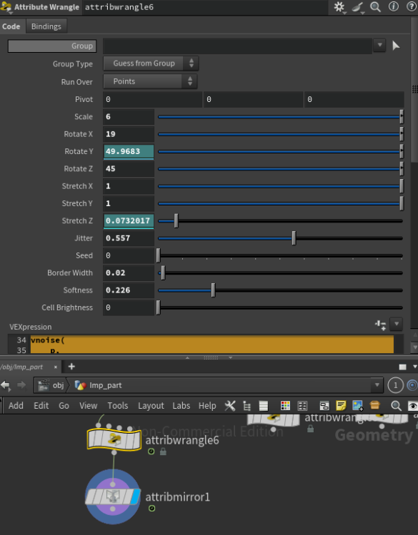
vector p = @P; // Center control, optional p -= chv("pivot"); // Scale the cellular pattern p *= chf("scale"); // Rotation controls in degrees float rx = radians(chf("rotate_x")); float ry = radians(chf("rotate_y")); float rz = radians(chf("rotate_z")); matrix3 m = ident(); rotate(m, rx, {1, 0, 0}); rotate(m, ry, {0, 1, 0}); rotate(m, rz, {0, 0, 1}); // Rotate the cellular noise space p *= m; // Directional stretch makes the rotation visible p.x *= chf("stretch_x"); p.y *= chf("stretch_y"); p.z *= chf("stretch_z"); float f1, f2; vector pos1, pos2; vnoise( p, chf("jitter"), chi("seed"), f1, f2, pos1, pos2 ); // Border calculation float edge = f2 - f1; float border = 1.0 - smooth( chf("border_width"), chf("border_width") + chf("softness"), edge ); // Cell color value float cell = rand(pos1 + chi("seed")); // Final result float result = lerp(cell * chf("cell_brightness"), 1.0, border); @Cd = set(result, result, result); f@cell_border = border; f@cell_value = cell; f@cell_result = result;1 point
-
1 point
-
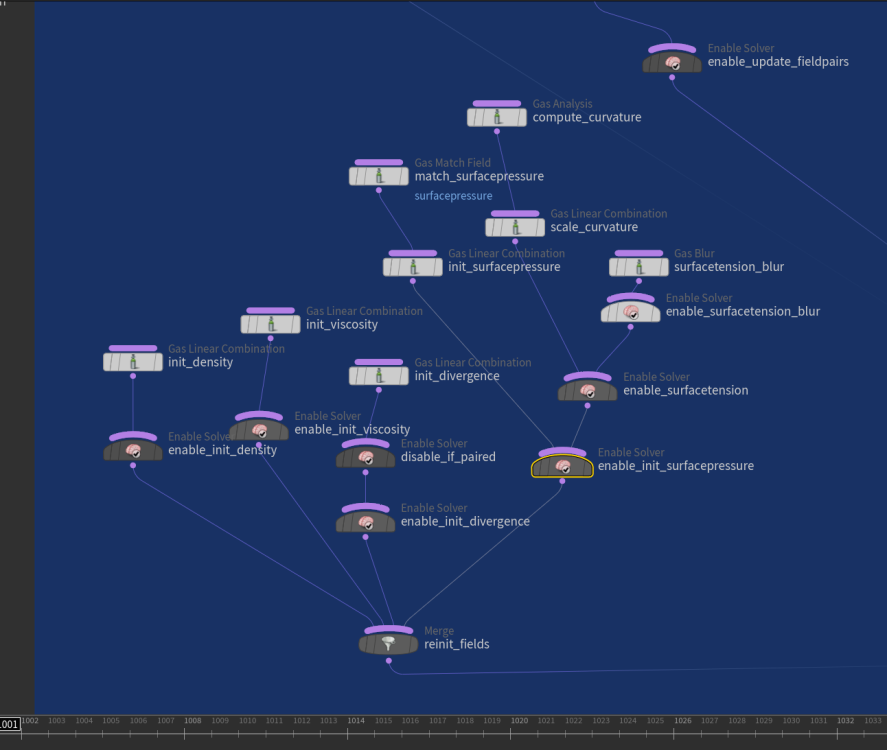
From what I understand: If you dive into the FLIP solver's Surface Tension feature, you'll find that the key parameter is the scale of curvature. The solver is based on the Navier-Stokes equations. It uses divergence to measure whether particle flow is shrinking or expanding, and then applies pressure to push or pull the fluid, ensuring incompressibility. With surface tension enabled, the solver applies surface pressure based on curvature. This pressure is summed and submitted during the pressure update step (FLIP solve), which then influences particle motion. In FLIP, the surface tension force is defined as: Code F = scale_ST × mean_curvature × surface_normal Where: F is the force density from surface tension FLIP Surface Tension parameter: scale_ST is the surface tension coefficient, typically based on particle separation or voxel size mean_curvature represents how much the surface is expanding, greater expansion leads to higher curvature magnitude surface_normal indicates the direction of the shrinking flow Here’s the link to the article I wrote, which includes a full default HIP file download with extra (paid) solution. It explains in detail why the method works (rock solid), how to use it, and offers various techniques to help you solve problems across different cases. https://medium.com/@vupham_37726/houdini-flip-surface-tension-demystified-f1239da880ce For more background, you might want to check out the paper “Continuum Surface Force Method.” It's important to note that the standard Navier–Stokes equations do not account for surface tension directly, they only solve for inertia, pressure, and viscosity. The Continuum Surface Force model is a technique used in computer graphics (CG) to inject surface tension behavior into fluid simulations. It’s designed for visual realism in animation, not for physically accurate modeling of real-world water materials. The blur radius feature acts as a smoothing filter to reduce volume noise and jitter. It uses a kernel radius to apply the blur. Increasing the blur radius reduces precision, which in turn diminishes fine details such as tendrils and thin films. The higher the scale ST, the stronger the surface tension pushes inward. Small droplets quickly transform into bulk spheres, and tendrils disappear faster. Reducing the scale ST makes films and tendrils harder to hold, causing them to scatter more quickly into floating dots. Maybe someone else could help make it easier to understand from an art direction or VFX perspective, rather than just explaining the dry technical details of the solver. One-day dev for this article and sample files, fueled by years of grind and the smart Houdini gang before me. I'm leaving it here for future reader.1 point
-
You can do this by typing the attribute type beforehand rather than the shorthand syntax. v@myvar = 123; This sets the default value to 0. vector @myvar = 123; This sets the default value to 123.1 point
-
1 point
-
1 point
-
not gonna pretend that I understand this technique but there were a few issues with syntax of parameters that probably changed throughout releases, so changed them and I think now it's working again here is the updated file volcano_001.hip edit: tried to wrap my head around it and copied the setup with the sparse solver: volcano.sparse.18.5.hip1 point
-
Some of your settings are bit strange, maybe you want to use them like that not sure. But i did some cleanup and tweaks to your initial tank, to use narrowband and adaptive solve to make it faster so you can push more details. broad_splash_02.hip1 point
-
Hi everybody! Check out my video about RnD of framework for robust OpenCL development. In this video I describe my old developement: framework for development GPU algorithms like cloth/wire/grains/particle/fluid dynamics. It is implemented as Python code snipped with set of extension functions for control some OpenCL specific tasks. It gives opportunity to develop complex algorithms without compilation, without HDK/C++, without even closing Houdini sessions.1 point
-
there were a few issues. 1) there was no velocity attribute before the rasterize_velocity node 2) pumps are affecting volume velocity so they need to be plugged in the volume velocity input of the Flip solver. 3) the FLIP object doesn't have a pump field by default in H18, you can create one and resize it. FluidPump_V02.hipnc1 point
-
I have a similar desire. My workaround for now has been to to create a label parameter for each parameter I want control over. Perhaps it will soothe your needs too until there's a better solution. For a left-justified label above the float(most easily accomplished) I would do the following: make a string: Strmylabel# -- you can add some kind of default expression to read in whatever you need or let the user adjust this -- if you are setting it yourself then make this parm invisible make a label: mylabel# -- turn off 'Main Label', turn on 'Horizontally Join to Next Parameter', and turn on all 16 labels -- In 'Label 1' put "<additional common words such as 'controls for: ' >`chs('Str' + substr($CH,0,strlen($CH) - 1 ))`<additional common words such as 'controls' or >" (you need '-1' because once you have more than Label 1 turned on the labels get additional #s added to the end so you don't want to get that number also) make a seperator: <doesn't matter> -- this will just help fill in rightspace so your label stays left-justified make a float: myfloat# -- turn off 'Main Label', setup however you want If the string parm is set to "hello3" and Label 1 has "Controls for: `chs('Str' + substr($CH,0,strlen($CH) - 1 ))` Objects" in Label 1 would yield the label: Controls for: hello3 Objects For right-justified labels that look like the normal label in-line with your float you can remove the seperater and move the Label expression to 'Label 16' replacing '-1' with '-2' since 16 is 2 digits long instead of 1 digit long. This method will force everything to the far right of the parameter interface You can do other similar things with attributes being read in using something like the following in the Label: `detailsmap(0,'myAttribute', opdigits( substr($CH,0,strlen($CH) )) )`1 point
-
POP Attract is unfortunately of pretty limited utility in a lot of situations. It does have a mode to attract to specific points or parametric locations on geometry (similar to the Creep SOP). You just need to provide the goal points to attract to. Scattering a number of points onto the goal sphere equal to your number of particles and giving them an i@id attribute to match with is an easy way to do this. You'll just have to deal with carefully fine-tuning your forces, because POP Attract only modifies the v@force attribute so there will be overshoot. If you want more control, it's not too hard to define the goal yourself in a POP Wrangle and bind it to some other attribute, such as the v@targetv wind force attribute. The VEX is pretty straightforward: // get matching goal point by id int match = idtopoint(1, i@id); // get vector to goal point vector goal = point(1, "P", match); // set targetv (wind force) to move towards goal. // targetv and airresist are the attributes generated by pop wind. vector targetv = (goal - @P) * ch("force_scale"); v@targetv = targetv; f@airresist = ch("air_resistance"); Those two attributes being bound at the end there are special attributes that the POP Wind DOP generates. The POP Solver uses these to define a target velocity and a bias for mixing with other wind forces. This lets you much more directly influence particle behavior. I'm attaching an example of both methods. pop_goal_methods.hiplc1 point
-
You're going to have a very very hard time with this technical exercise of wrapping a rotating cloth around and around a small tube. This is a non trivial problem. You may need to crank up certain values like the density of points on the geometry or crank up the overall substeps to such a point that it either blows up or just barely works. In other words Vellum, IMHO, isn't designed for wrapping and sticking cloth. Instead I think it's designed more for draping cloth style with one or two wrinkles, not eight layers. But I'd be grateful if you proved me wrong and were able to find the right settings. To that end you'll want to change your polygon group selections to a more procedural nature and use a bounding box instead of an explicit manual selection of certain numbered polys. That way you can change your geometry more easily. Is this for a specific effect in a shot that you're working on? Is it a personal challenge? Is it for a class? There might be another way to solve this as a visual problem instead of a naive simulation. I would suggest a more manual animation style or blend shape style solution if you need a ring of cloth wrapped around a pole.1 point
-
And a simple example file attached this time... lidar2heightfield_bunker_01.hipnc1 point
-
Hey James, I would approach it in a different way, check it out: first of all, packed rigid bodies act like particles so you can use the pop wind instead of the wind force (and all the other pop forces, this give us a lot of forces varieties) Here's how you can set this up: To make statement run multiple times it must be inside the dop network (use a popwrangle for this) Idk how to make the pieces scale up or down using vex (never thought of that) so I would do it using the primitive sop. To use the primitive sop you will need a sop solver. To use the sop solver with the bullet solver you must connect both using a Multi Solver (I know, it looks complex but it's a very common technique, you will see yourself doing a lot of multisolvers in th future) Here's how it should looks like: Inisde the sop solver you can set things like this and use the scale parameter to scale individual pieces based on some other attribute (age in this situation) (Inside the sop solver you can do stuff you'd do in sop context, affecting the dop net stuff) It looks like it's working fine now, I hope it can makes some things clear for you Cheers, Alvaro Plant Debris scale_fix_02.hipnc1 point
-
Solved by Peter Sanitra @ Redshift Render community facebook group. Uploading the updated hip file. So: 1. you have to compute the velocity of points before the boolean, then use a atribute transfer to transfer the velocity from that preboolean to the new boolean geo. 2. go to redshift per object parameters (OBJ level) - Settings - Render and activate Deformation Blur From Velocity Attribute , so you force redshift to compute the motion from your velocity atribute from points. Done! I hope my full morning investigation will be usefull for you guys! Keep growing! mberror_solved.hiplc1 point