 |
VOOZH | about |
|
VOOZH | about |
Arduino IDE (Integrated Development Environment) is an important software used for writing and uploading programs to Arduino boards. It provides a simple and user-friendly platform where coding can be done using high-level languages such as C and C++. This makes programming easier compared to low-level assembly language programming.
Arduino coding involves understanding different commands, functions, variables, and syntax used to control hardware components connected to the Arduino board. Before starting, it is important to install a suitable version of the Arduino IDE on your computer. Once the IDE is ready, you can begin learning the basics of Arduino programming and practice writing programs directly in the software.
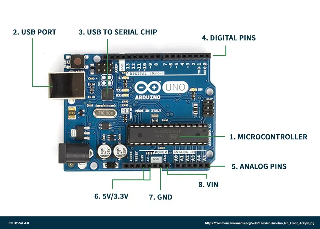
An open-source electronics platform used to program and control electronic devices. It consists of components such as a microcontroller, digital and analog pins, power supply connections, and crystal oscillators. Arduino allows users to create projects like LED control, robotics, automation systems, and sensor-based applications easily. Its simple programming environment and flexible hardware make it popular among students, beginners, and professionals.
Analog Signal: Take any value in a given continuous range of values. Generally, analog signals used in Arduino are around 0V to 5V. The analog pins can take data up to 8-bit resolution therefore, they are used for taking large values as input in the Arduino. These signals carry data in a very accurate form without many errors.
Digital Signal: Only take discrete values which are, high('1') and low('0'). These signals are usually used to Arduino on or off which requires only two values. The collection of two values (0 and 1) can be used to generate a sequence known as the binary sequence which is a collection of zeroes and ones. This is how data is transmitted without much memory requirement but this can lead to certain errors like quantization errors.
Parentheses: When writing a function in IDE, the parentheses brackets are used to include the argument parameters, such as methods, functions, or code statements. In addition to this, the bracket is also used for defining the precedence order while dealing with mathematical equations. These brackets are represented by '( )'.
Curly Brackets: Used to open and close all the statements in the functions or out of the functions. Note that a closed curly bracket always follows the open curly bracket in the code for proper layout. These brackets are denoted by '{ }'.
// This is a comment
/ * This is a multiline comment
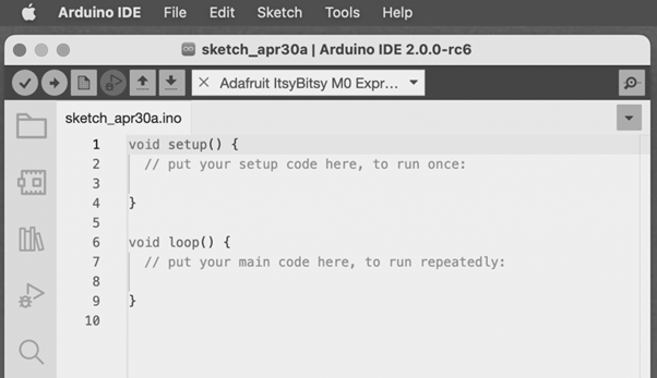
If you open the coding screen of your IDE, you will realize that it is divided into two sections namely, setup() and loop(). The setup segment is the first block and is implemented first for preparing the necessary environment needed for running other commands. This coding screen is shown below:
It is important to note that the setup and loop blocks must have statements that are enclosed within curly brackets. Depending on the type of project you are working on, you can initialize the setup in setup() and define other necessary statements in the loop() block.
For example
void setup ( ) {
Coding statement 1;
Coding statement 2;
Coding statement n;
}
void loop ( ) {
Coding statement 1;
Coding statement 2;
Coding statement n;
}
Contains the very beginning section of the code that must be executed first. The pin modes, libraries, variables, etc., are included in the setup section so that no problem occurs when the remaining code runs. It is executed only once during the uploading of the program and after resetting or powering up the Arduino board.
Zero setup () resides at the top of each sketch. When the program runs after completion, it heads towards the setup section to initialize the setup and include all the necessary libraries all at once.
Contains statements that are executed repeatedly. Unlike, the setup section there is no restriction on running this code once, it can run multiple times according to the value of variables.
Basic unit of measuring time in Arduino programming is a millisecond.
1 sec = 1000 milliseconds
Timing adjustments can be made in milliseconds. A better explanation for this can be that a 2-second delay corresponds to 2000 milliseconds.
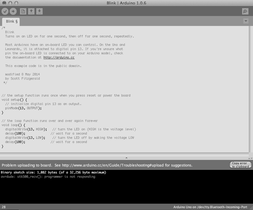
A simple example of blinking the LED using Arduino is considered.
The steps are:
This is the window that opens:
Note: The pinMode will be the main function in the void setup() and digitalWrite( ) and delay ( ) will be the main function in the void setup()
The pinMode() function assigns a specific PIN as either INPUT or OUTPUT.
Syntax
pinMode (pin, mode)
Pin: It is used to specify the PIN which depends on the project requirements.
Mode: Depending on whether the pin is taking INPUT or OUTPUT, it specifies the pin's function.
Let's consider a situation to understand the pinMode. We want to take input from the PIN 13 and then,
Code:
pinMode (13, INPUT);
Setting pinMode to OUTPUT is important for some pins. This mode allows the specified PIN to supply sufficient current to another circuit to activate the sensor or light the LED. When set to OUTPUT, this pin goes into a very low impedance state, making the current useful. It is important to note that excessive current or short circuits between pins can damage the Atmel chip. This explains the need for setting the mode to OUTPUT.
When digitalWrite() is used, selecting the INPUT mode for any pin turns off the low state and sets the high state as the ultimate state. The INPUT mode can be employed alongside an external pull-down resistor. For this purpose, pinMode should be set to INPUT_PULLUP. This configuration reverses the behavior of the INPUT mode. In INPUT_PULLUP mode, a sufficient current is provided to light an LED connected to the pin dimly. If the LED emits a dim light, it signifies that this condition is operational.
Given these considerations, it's advisable to set the pin to OUTPUT mode to ensure proper functionality.
The digitalWrite( ) function is used to decide the value of the pin. It can be set as either of the two values, HIGH or LOW.
If no pin is set with pinMode as OUTPUT, the LED may light dim.
Syntax
digitalWrite( pin, value HIGH/LOW)
Pin: We can specify the PIN or the declared variable.
Let's understand with an example.
Example:
digitalWrite (6, HIGH);
digitalWrite (6, LOW);
The HIGH will be used for setting the pin at number 6 high and it will ultimately turn on the LED if connected to this pin while, the LOW will be used for setting the pin at number 6 low and it will ultimately turn off the LED if connected to this pin.
The delay() function serves as a tool to halt program execution for a specified duration, measured in milliseconds. We have seen how delay(5000) signifies a stop of 5 seconds.
This can be understood by the fact that 1 second equals 1000 milliseconds.
Code:
digitalWrite (12, HIGH);
delay (5000);
digitalWrite (12, LOW);
delay (2000);
The program here is that the LED is connected to the pin having PIN 12 and it will remain lit for 5 seconds before turning and then will go off. The LED will then be turned off for 2 seconds as specified by delay(). This cycle will continue in a loop depending on the defined variables within the void loop() function.
Pseudocode:
Firstly, we will need to set a particular pin as the output pin therefore, we will set the pin number 12 as the input in setup() block.
Then we need to set the pin number 12 high using the digitalWrite() function.
Then we use the delay() function to keep the LED on for 3 seconds.
Then we need to set the pin number 12 low using the digitalWrite() function.
Then we use the delay() function to keep the LED off for 2.5 seconds.
Code: