 |
VOOZH | about |
|
VOOZH | about |
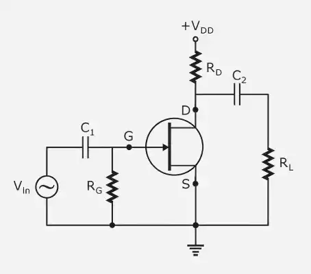
A JFET amplifier's frequency response explains how the amplifier's gain changes with frequency. At all frequencies, the amplifier's gain is not consistent. Rather, the gain falls at low and high frequencies and stays about constant in the mid-frequency region.
Capacitors reactance greatly increases at low frequencies. Consequently, coupling and bypass capacitors start to influence the signal instead of functioning as short circuits.
Two RC networks affect the low-frequency response of a typical JFET amplifier:
The amplifier's lower cutoff frequency is determined by these RC networks.
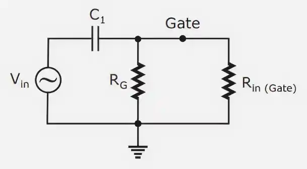
The input coupling capacitor and the amplifier's input resistance combine to generate the input RC network.
Working
Equivalent Resistance
Since the gate current is very small, the input resistance is usually very high.
Lower Cutoff Frequency
This frequency establishes the threshold below which the input network causes the gain to begin declining.
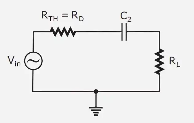
The circuit is output resistance and output coupling capacitor combine to form the output RC network.
Working
Equivalent Resistance
Lower Cutoff Frequency
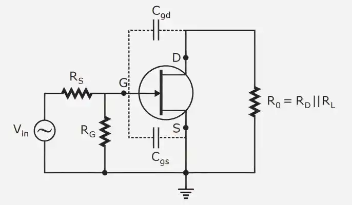
The coupling and bypass capacitors function as short circuits at high frequencies and have no effect on the behavior of the circuit. Rather, the JFET's intrinsic capacitances start to matter.
The following internal capacitances are crucial:
The high-frequency response is impacted by the additional RC networks introduced by these capacitances.
Between the input and output terminals is the capacitance (). Miller's theorem significantly increases this capacitance due to amplification.
The capacitances that are equivalent are:
As a result, the high-frequency performance is decreased and the effective input capacitance is increased.
The high-frequency input RC network is created by:
Cutoff Frequency
This determines the upper cutoff frequency due to the input side.
The output RC network is formed by:
Cutoff Frequency