 |
VOOZH | about |
|
VOOZH | about |
Implementation of the NOR gate from the NAND gate is possible because NAND is a Universal gate i.e., it can implement all other gates. The NAND gate gives output low when all the inputs are high whereas the NOR gate gives output high when all inputs are low. In this article, we will implement the NOR gate using the NAND gate.
Table of Content
NOR gate is a logic gate that gives output 1 when all the inputs are 0. In other words, the output is high when all inputs are low. NOR gate is a Universal gate. It is the complement of the OR gate.
The NOR gate with 2 inputs is called a 2-input NOR gate. It gives the output high when both the inputs are low.
The following truth table represents the NOR gate.
A | B | A NOR B |
|---|---|---|
0 | 0 | 1 |
0 | 1 | 0 |
1 | 0 | 0 |
1 | 1 | 0 |
From the above truth table, expression for NOR gate is:
A NOR B = A'B' = (A + B)'
Below is the logic diagram for NOR gate.
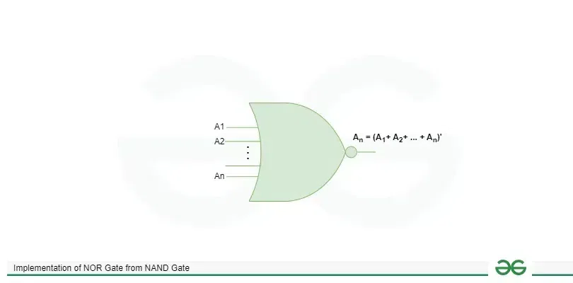
The NOR gate with n-inputs is called as n-input NOR gate. It gives the output high when all the inputs are low otherwise output is low. In other words, the output is low when any one of the inputs among n inputs is high.
If the inputs are A1, A2, ..., An then,
A1 NOR A2 NOR ...NOR An = (A1+ A2+ ... + An)'
Below is the logic diagram for n-input NOR gate.
NAND gate is a logic gate which gives output 0 when all the inputs are 1. In other words, the output is low when all inputs are high. It gives output high if at least one input is low. NAND gate is a Universal gate. It is the complement of AND gate.
A 2-input NAND gate is a logic gate which gives output high when at least one input is low. It gives low output when both the inputs are high.
The following truth table represents the NAND gate.
A | B | A NAND B |
|---|---|---|
0 | 0 | 1 |
0 | 1 | 1 |
1 | 0 | 1 |
1 | 1 | 0 |
From the above truth table expression for NAND gate is:
A NAND B = A'B' + A'B + AB'
A NAND B = A' + B' = (A.B)'
Below is the logic diagram of NAND gate.
The NAND gate with n inputs is called n-input NAND gate. In this logic gate the output is low when all the inputs are high otherwise the output is high.
If the inputs are A1, A2, ..., An then,
A1 NAND A2 NAND ...NAND An = (A1. A2. ... An)'
Below is the logic diagram for n-input NAND gate.
Following is the implementation of NOR gate from NAND gate. First, we produce complements of inputs and further implement NOR logic.
Below is the logic diagram for the implementation of NOR gate from NAND gate.
So,This is How the NAND gate can be Implemented as NOR gate.
From the above discussion we can conclude that to implement NOR gate from NAND gate we require 4 NAND gates. First two gates give us the complement of the inputs and then, we connect two more NAND gates to get NOR gate. We also use DE Morgan's law to convert and of individual complements to whole complement of OR of inputs.