 |
VOOZH | about |
|
VOOZH | about |
Because a JFET can regulate drain current using the gate-to-source voltage, it can be utilized as an amplifier. A slight change in input voltage causes a large change in drain current, which leads to amplification because the gate current is almost zero.
The JFET's voltage-controlled design serves as the foundation for the amplification process. The drain current is altered when an input signal is applied at the gate due to changes in . The output voltage is increased as a result of the voltage drop across the drain resistor caused by the fluctuating drain current.
JFET amplifiers are frequently utilized because
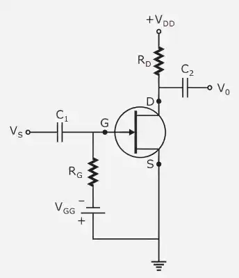
Most used setup for JFET amplifiers. The input signal is applied between the gate and the source in this circuit, and the output is obtained between the drain and the source.
Both input and output share the source terminal.
There is a phase shift between the input and output due to the amplification and inversion of the output signal.
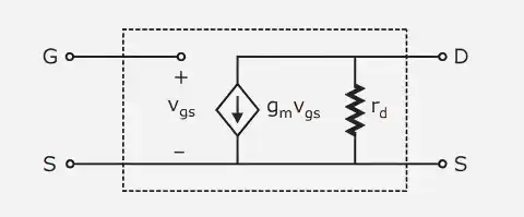
For analysis at mid-frequency:
Included in the tiny signal model are:
These characteristics are used to examine the amplifier's impedance and voltage gain.
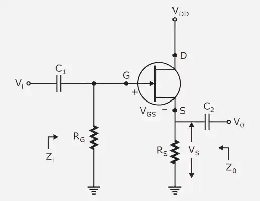
The drain terminal of the common drain (CD) amplifier, sometimes referred to as a source follower, is shared by the input and output. The output is taken between the source and the drain, while the input signal is applied between the gate and the drain.
Input impedance:
Output impedance:
Voltage gain:
If , then:
This configuration is mainly used as a buffer stage.
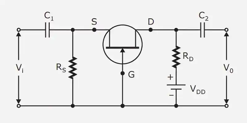
The gate terminal in the common gate (CG) design is shared by the input and output. The output is taken between the drain and the gate, while the input signal is applied between the source and the gate.
Typically, the potential of the gate is constant.
There is no phase shift between the input and output, in contrast to a common source amplifier.
Input impedance:
Output impedance:
Voltage gain:
assuming
This configuration is suitable for high-frequency applications due to its low input impedance and reduced Miller effect.