 |
VOOZH | about |
|
VOOZH | about |
Applying appropriate voltages and currents to a transistor to cause it to function in a desired region of its properties is known as biasing. Appropriate biasing in JFET circuits guarantees that the device runs in the saturation region, where it can efficiently perform as an amplifier.
Drain current can vary significantly due to changes in device characteristics, just like in transistor circuits. Biasing networks are therefore made to sustain steady operating conditions in spite of these fluctuations.
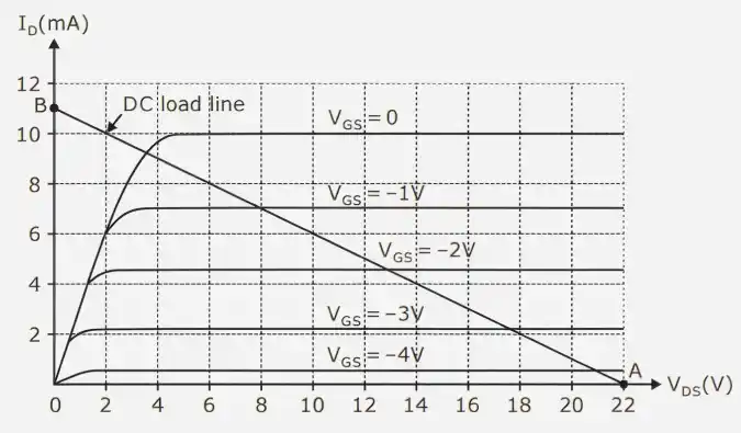
The DC load line represents all possible combinations of drain current and drain-to-source voltage for a given circuit.
It is obtained using Kirchhoff’s Voltage Law (KVL) applied to the drain circuit:
Rewriting,
This equation represents a straight line on the versus graph.
Key Points of Load Line
When
When
Joining these two points gives the DC load line. This line is used along with device characteristics to determine the operating point.
The point on the characteristics curve that shows the steady-state drain current and drain-source voltage values in the absence of an input signal.
It is acquired as the point where:
A well-selected Q-point guarantees:
Significant Q-point shifts could result in distortion or incorrect amplifier functioning.
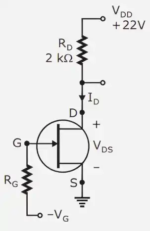
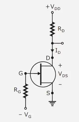
Through a resistor , a set voltage is applied to the gate in the gate bias circuit.
Shockley's equation can be used to determine the drain current:
Within this circuit:
Although this approach is straightforward, it has a significant drawback: it does not offer stability against changes in device characteristics.
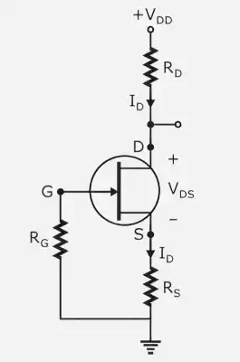
In the self-bias design, a resistor attached to the source terminal automatically develops the gate-source voltage.
Given that gate current is very small:
Thus,
This demonstrates how the drain current affects the gate-source voltage.
The self-bias circuit provides negative feedback:
Similarly:
Applying KVL:
This circuit provides better stability compared to gate bias.
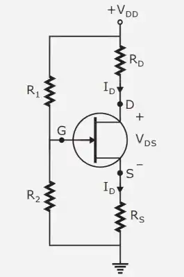
An enhanced form of the self-bias circuit is the voltage divider bias circuit. It provides a fixed gate voltage by using two resistors, and .
The following yields the gate voltage:
The voltage at the source is:
Thus,
Compared to self-bias: