 |
VOOZH | about |
|
VOOZH | about |
The behavior of a Junction Field Effect Transistor (JFET) under various electrical situations is described by its characteristics. Important factors including drain current (), gate-to-source voltage (), and drain-to-source voltage () are established by these features.
Analyzing JFET operation in switching and amplifier circuits requires an understanding of these features. Two characteristic curves are primarily used to explain the behavior of a JFET:
These curves shed light on how changing the applied voltages can regulate the device's current.
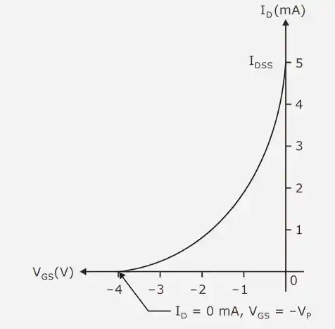
Transfer characteristics show how the drain current varies in relation to the gate-to-source voltage while maintaining a high enough drain-to-source voltage to allow the device to function in the saturation area.
The gate-source junction of a JFET is always reverse biased. Because of this, the gate current is incredibly little and is typically disregarded in analysis. The electric field produced by the gate voltage alone is responsible for controlling the drain current.
Shockley's equation describes the non-linear relationship between and :
where
The parabolic curve that results shows that the current change is not linear in relation to the gate voltage.
The transconductance of the device, a crucial parameter in amplifier analysis, is determined by the slope of the transfer characteristic curve at any given location.
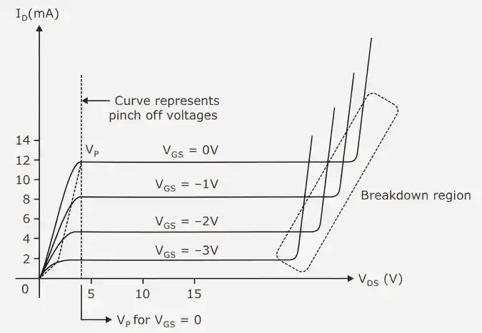
Drain characteristics display how the drain current changes in relation to the drain-to-source voltage for various gate-to-source voltage values.
The channel exhibits resistive path behavior when a tiny value of is applied. According to Ohm's law, the current rises roughly linearly with voltage.
The voltage drop down the channel is not uniform as rises. Near the drain end, the reverse bias across the gate-channel junction increases in importance. As a result, the channel gradually narrows as the depletion region grows closer to the drain.
Near the drain end, the channel narrows significantly at a specific value of . We call this situation pinch-off. After this, the drain current approaches a constant value and does not rise much with any increases in .
The electric field in the depletion region keeps current flowing even though the channel looks narrow.
For varying values of , different curves are obtained. When reverse prejudice becomes more pronounced:
Based on the drain characteristics, the operation of a JFET can be divided into three regions.
At low values of , the ohmic region is present. The gadget acts as a linear resistor in this area since the channel is wide.
When the JFET is utilized as a voltage-controlled resistor, this area is helpful.
The JFET enters the saturation region when rises above a specific threshold. The current becomes nearly constant in this area as the channel close to the drain gets choked off.
Because it enables the device to provide steady gain, this is the most crucial area for amplifier operation.
The device reaches the breakdown region if the drain-to-source voltage is raised above a safe threshold.
In practical applications, this area is typically avoided to guarantee safe functioning.