 |
VOOZH | about |
|
VOOZH | about |
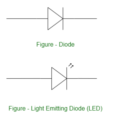
We will interface an LED (light-emitting diode) to the Arduino UNO board. An LED is a simple diode that emits light in a forward bias. We will write an LED-blinking program on the Arduino IDE and download it to the microcontroller board. The program simply turns ON and OFF LED with some delay between them.
Arduino is an open-source, board that has a Microchip ATmega328P microcontroller on it. This microcontroller has a set of Digital & Analog input and output pins. The operating voltage of the board is 5V. It has 14 digital I/O pins & 6 Analog input pins. The clock frequency of the microcontroller is 16 MHz.
LEDs (Light Emitting Diodes) are becoming increasingly popular among a wide range of people. When a voltage is given to a PN Junction Diode, electrons, and holes recombine in the PN Junction and release energy in the form of light (Photons). An LED's electrical sign is comparable to that of a PN Junction Diode. When free electrons in the conduction band recombine with holes in the valence band in forward bias, energy is released in the form of light.
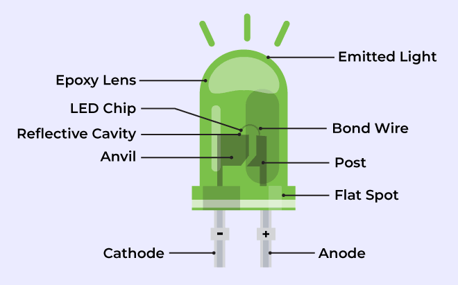
👁 What is LEDThe flow of charge carriers (electrons and holes) across the P-N junction drives the activity of an LED. When a forward voltage (anode positive in comparison to the cathode) is applied, electrons and holes recombine at the junction, releasing energy in the form of photons (light). The semiconductor chip is linked to external terminals known as the anode (+) and the cathode (-). The anode is linked to the P-region, and the cathode to the N-region.
Blinking an LED is an introductory Arduino project in which we control an LED using Arduino. LED blinking refers to the process of continuously turning an LED (Light Emitting Diode) and off in a repetitive pattern. It is a simple and common demonstration in electronics and microcontroller-based projects.
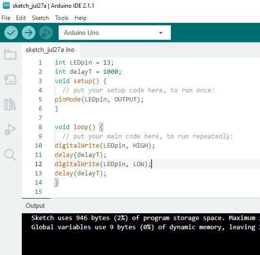
setup() and loop() are two fundamental Arduino functions for controlling the behavior of your board. The Arduino framework automatically calls these functions, which form the foundation of any Arduino program.
The setup() function is only called once when the Arduino board boots up or is reset. Its goal is to set pin modes, initialize variables, and execute any other necessary setup tasks before the main loop begins. This function can be used to configure settings that should only be changed once over the board's lifespan.
The loop() function is the heart of an Arduino program. After the setup() function is executed, the loop() function starts running repeatedly until the Arduino is powered off or reset. It contains the main code that performs the desired tasks, controls the board, user input. Whatever is included in the loop() function will be executed in a continuous loop, allowing the Arduino to perform its intended functions continuously.
In the code, we have declared two integers, LEDpin and delayT. LEDpin represents the pin number of the Arduino where LEDs need to be connected, and delayT is an integer variable for the delay() function. The delay() function accepts values in milliseconds.
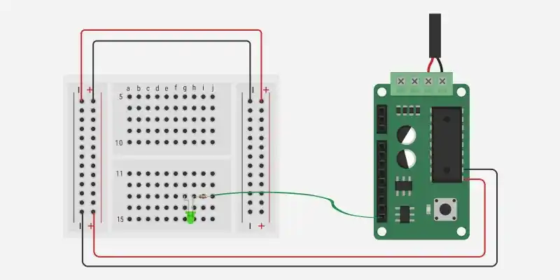
In the circuit diagram, we used one 330-ohm resistor in series with the LED. This resistor is also called a current-limiting resistor. The Anode of the LED (the longer pin) is connected to one end of the resistor, and the cathode (the shorter pin) is connected to the ground. The other end of the resistor is connected to the Arduino pin. A step-by-step explanation is as follows:
The circuit is now complete. Here's how it works:
When you upload a simple Arduino program that controls the LED, the microcontroller on the Arduino board executes the program, and the LED will blink according to the code you wrote.
The LED blinking project is an important and straightforward method that can be utilized for a wide range of applications in microcontroller-based projects like :