 |
VOOZH | about |
|
VOOZH | about |
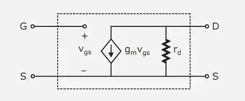
A JFET's behavior is represented by the small signal model in terms of tiny variations in voltage and current.
Within this model:
The JFET tiny signal model's essential elements are:
The link between the change in gate-source voltage and the change in drain current.
It indicates how effectively the input voltage controls the output current.
Represents the output resistance of the JFET due to channel length modulation.
It models the variation of drain current with drain-source voltage in the saturation region.
The main element of the model is a dependent current source given by:
This shows that the output current is controlled by the input voltage, confirming the voltage-controlled nature of the JFET.
The entire tiny signal model is made up of:
This model is used to analyze mid-frequency amplifier circuits.
Obtained by altering the original amplifier circuit to exclusively take AC components into account.
Analyzing gain and impedance without the impact of DC biasing is made easier by this simplification.
Following these procedures, the circuit transforms into a linear AC network that can be examined using conventional methods.
Once the AC equivalent circuit is obtained, the following parameters can be determined:
Voltage Gain
Ratio of output voltage to input voltage.
For a common source amplifier:
assuming
Input Impedance
The input impedance of a JFET amplifier is very high due to negligible gate current.
where, is the gate resistance
Output Impedance
Determined by the drain resistance and external resistors.
A key component in comprehending and creating JFET amplifiers is small signal analysis. It helps in: