 |
VOOZH | about |
|
VOOZH | about |
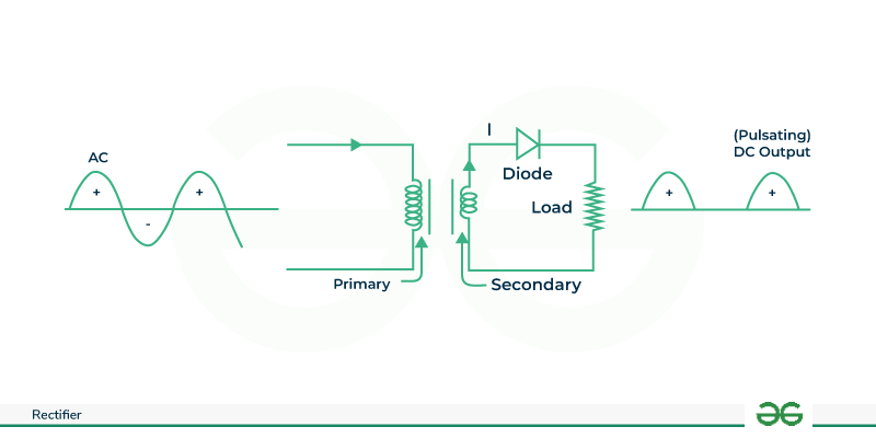
A Rectifier is an electronic device that converts the alternating current (AC) into direct current (DC) by allowing a current to flow through the device in one direction only using one or more P-N junction diodes. Many circuits use DC voltage for operation. It can easily convert AC voltage or current into DC or voltage. A P-N junction diode allows the current to flow in a forward bias condition and blocks the current in a reverse bias condition. More simply we can say that a diode allows electric current to flow in a single direction. This property of the diode allows it to act as a rectifier and the process is called rectification.
Table of Content
A rectifier is an electrical device that converts Alternating Current (AC) into Direct Current (DC) by using one or more P-N junction diodes.
When a voltage is applied on the P-N junction diode in a way that the positive terminal (+ve) of the battery is connected to the P-type semiconductor and the negative terminal(-ve) of the battery and is connected to the N-type semiconductor called forward biased. When the forward bias voltage is applied to the P-N junction diode the large number of free electrons (e-) (majority carriers) in the N-type semiconductor experiences a repulsive force from the negative terminal of batter and similarly, the large number of holes(majority carriers) in the p-type semiconductor experiences a large repulsive force from the positive terminal of the battery.
As a result, the free electron in the N-type semiconductor moves from the N-side to the P-side and as such the holes in the P-type semiconductor start to move from the P to the N-side. As we know the current means flow of charges (free electrons and holes). So, the flow of the electrons from the N-side to the P-side and the holes flow from the P to the N side which conduct electric current. The maximum number of carriers produces the electric current in the forward bias. So the current produced in the forward bias is also called majority current.
When the voltage is applied to the P-N junction diode in such a manner that the positive terminal of the battery is connected to the N-type and the negative terminal of the battery is connected to the P-type then the diode is reverse biased.
So when this reverse bias voltage is applied to the P-N junction diode, the large of free electrons in the N-type experience an attractive force from the positive terminal of the battery, in the same manner, a large number of holes in the P-type experience an attractive force from the negative terminal of the battery.
As a result of reverse bias the free electrons in the N-type semiconductor move away from the P-N junction and are attracted to the positive terminal of the battery. At the same, the holes in the P-type move away from the P-N junction and are attracted to the negative terminal of the battery. The electric flow does not occur across the P-N junction. The minority carrier in the P-type experiences a repulsive force from the negative terminal of the battery and as same the minority carrier in the N-type experiences a repulsive force from the positive terminal of the battery. As a result, the minority carriers free electrons in the P-type semiconductors and the minority carriers holes in the N-type start flowing in the junction. The electric current is produced by the minority carriers in very small. So the minority carrier current in the reverse bias is neglected.
The P-N junction allows the current in the forward bias and blocks the current in the reverse bias. In simple words the P-N unction allows electric current in one direction only. This unique property of the diode allows it to behave like a rectifier.
Rectifiers are classified into two types:
The rectifier whose voltage is not controlled is known as an Uncontrolled rectifier.
Uncontrolled AC half-wave further divided as follows :
The rectifier that converts half cycle of the AC in the DC is called a half wave rectifier.
Similar to this a full-wave rectifier converts the positive and negative half cycle of the AC.
The Half-wave rectifier converts the AC signal to a DC signal by passing the signal to either a negative or positive half-cycle of waveform while blocking the other half-cycle. It can easily constructed using a single diode. As we know diodes can only carry current in a single direction, they work as sample half-wave rectifiers.
The half-wave rectifier is made of 3 components:-
Now we are deep down in understanding how a half-wave rectifier transforms AC signal to DC.
Now we will simplify the half-wave rectifier circuit by replacing the secondary coil with a voltage source
Now for the positive half side of the AC voltage source, the circuit will be
Whenever the diode of the circuit is in forward bias it works as a closed switch but when it is in the negative half cycle the AC voltage source is equivalent to
When the diode is reverse-biased, the circuit acts as an open switch.
In the positive half wave rectifier only the positive half wave cycle of the AC current allowed to flow through the circuit while the negative half wave cycle get blocked this can be achieved by using single diode in the circuit.
In the negative half wave rectifier only the negative half wave cycle of the AC current allowed to flow though the circuit while the positive half wave cycle get blocked this can be achieved by reversing the orientation of diode used in the positive half wave rectifier.
A full-wave rectifier is a circuit that converts the full cycle of AC into pulsating DC. Unlike a wave that only utilizes one half of the input cycle a full wave rectifier takes advantage of both the positive and negative halves of the input cycle resulting in a smoother and more efficient output.
For full wave rectifiers, we can design the circuit in two ways.
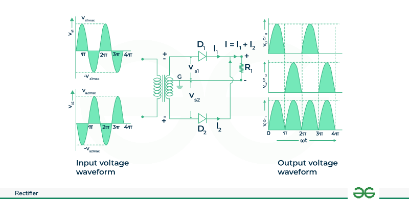
A circuit that has a step-down transformer with two diodes is connected and tapped in the center.
There are some list of full wave rectifier formulas given below :
PIV across D1 and D2 is 2Vmax
The full wave rectifier is further classified into two types :
When an input AC is supplied the to circuit the step-down transformer in the rectifier converts the high-voltage AC into low-voltage AC. The anode part of the circuit which is tapped in the center is connected to the transformer's secondary winding and also same is connected to the load register. When the positive(+ve) has a cycle of the AC the upper half of the secondary winding becomes negative(-ve).
In the positive half cycle diode D1 is in a forward bias state as it is connected to the top of the secondary winding and diode D2 is in reverse bias as it is connected to the bottom part. Due to this D1 will act as a short circuit and D2 will act as an open circuit.
When the circuit is in the negative half cycle the D1 diode is reverse biased and the D2 is forward biased because the top half of the secondary circuit becomes negative and the other half becomes positive.
Different parts of electronics require a rectified DC power supply to power various electronic basic components from the available AC main supply. Among the rectifiers, the bridges are the most efficient rectifier circuit. The bridge rectifier is a type of full wave rectifier that uses four or more diodes in a circuit to efficiently convert AC to DC.
The bridge rectifier is made of four diodes let's say D1, D2, D3, D4, and a load register RLan. All the diodes are connected with each other in a closed loop so that it can efficiently convert the AC to DC. The advantage of this configuration is the absence of an expensive center-trapped transformer.
An input signal is applied to terminals A and B, the output DC signal is obtained through the load register RL connected between terminals C and D. All 4 diodes are arranged in such a way that only 2 of the diodes conduct electricity during each occurring half cycle. The diode D12 and D4 conduct the electric current during the negative half cycle.
Working of Bridge Rectifier
When the AC signal is supplied across the bridge rectifier, the terminal A becomes positive during half cycle and the B terminal becomes negative. This results in the D1 and D3 being in forward bias while D2 and D4 are in reverse bias.
So, during this negative cycle, terminal B becomes positive, and terminal B becomes negative. It results in diode D2 and D4 in forward bias and D1 and D3 diodes are in reverse direction.
From the above discussion, we observed that the current flow in load register RL is the same in both cycles (during the positive and negative half cycle). The output DC signal polarity may be either positive or negative.
Hence a bridge rectifier allows electric current during both positive and negative half cycles of the input AC signal.
It is a type of rectifier which uses the center tapped transformer in order to convert AC signal to DC signals and also it uses two diodes for this. It allows the electric current to pass on in the positive and negative half cycles of the input AC signals, it uses center tapped transformer as its input. The efficiency of the circuit is high as the AC supply brings the power with the both halves of the cycle.
At the output of the center tap rectifier or the circuit, in order to make the stable DC output the ripple gets eliminated by the capacitor.
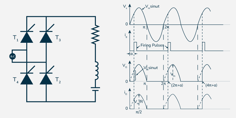
A rectifier whose voltage can be controlled means can be varied is known as a controlled rectifier. For controlling we use SCRs, MOSFET, and IGBT to make the uncontrolled rectifier into a controlled rectifier. These are proffered over the uncontrolled counterparts.
As the SCRs gets on or off at the gate signals then the complete control is established in the rectifier. The gate output is responsible for the controlling of the output voltage .
In a Half wave controlled rectifier, input AC voltage control only one half cycle of the voltage. It is regulated by using a thyristor to control the current flow. Thyristor turned on when the input AC voltage half-cycle comes allowing current to flow hence one-cycle-half waveforms are generated at the output resulting into generation of DC waveform only on one half cycle as shown below. Therefore, half wave controlled rectifier cannot regulate output DC waveform as compared to full wave controlled rectifier.
In full wave control rectification, both half-cycles are controlled. Thyristors are employed in to regulate currents flowing in either direction. The administering of control signals to turn ON the thyristors; which conduct during both half-cycles of the input AC voltages, results into flowing across them leading to production of DC with complete cycle waveshape output. Constructed with HTML tags. Is well as bursts than perplexing; even though the number of words has not been changed.
A control bridge rectifier is a circuit that converts alternating current to direct current using four diodes in bridge configuration. It uses thyristors or similar devices to regulate the output voltage. The bridge rectifier's output voltage and current can be regulated or adjusted as necessary by addition of these extra control components. This feature brings about a finer control of the DC output and is what makes the control bridge rectifiers appropriate for applications requiring variable DC outputs such as motor speed control, power supplies, and battery charging systems.
The main application of rectifiers is to derive DC power from AC power. These are used in the power supplies of all types of electronic equipment. In power supplies, the rectifier is generally placed in series following the transformer, smoothing filter, and voltage regulator.
Properties | Half-Wave Rectifier | Full Wave Rectifier |
|---|---|---|
Definition | Converts one-half of AC input into DC output | Converts both halves of AC input into DC input |
Complexity | Consist of a single diode | It consists of a minimum of 2 diodes. |
Efficiency | It utilizes only half the AC cycle. | It utilizes the complete AC cycle. |
Voltage Regulation | Poor | Good |
Output Frequency | Equal to the input frequency | Twice the input frequency use both cycles. |
Output Voltage | Vavg = | Vavg = |
Rectification Efficiency | 40.6% approx. | 81.2% approx. |
Application | Used for Low-Power application | used in high power supply. |
In conclusion, Rectifier plays an important role in converting AC to DC voltages. We have seen the working of Half-wave and full-wave rectifiers with differences between half-wave and full-wave rectifiers. We have also discussed several Applications of rectifier with their advantages and disadvantages. So basically it is a device which is used to convert AC signal to DC signal. The rectifier can take the shape of several physical forms like solid state diodes, vacuum tube diodes, mercury-arc valves, and other silicon-based semiconductor switches.
The P-N junction allows the current in the forward bias and blocks the current in the reverse bias. In simple words the P-N unction allows electric current in one direction only. This unique property of the diode allows it to behave like a rectifier.
-(1).webp)