 |
VOOZH | about |
|
VOOZH | about |
As we know electricity is generated at power generation plants using huge electromechanical generators by conversion from different types of energy. After that, a long-distance transmission line carries this electrical energy to the end users. In order to maximize the effectiveness of the power transmission and distribution system and ensure the safety of the connected loads and personnel, the electrical power transmission lines require a variety of safety devices and components. The transmission line faces different types of losses and characteristics that influence its efficiency. The Ferranti Effect is one such phenomenon that has a significant impact on the transmission line.
For the most part, we assume that the voltage generally drops in the transmission lines because of the line losses. In a long-distance transmission line with a very low load or no load at all, the Ferranti Effect causes the receiving voltage to be higher than the sending voltage.
In this article, we will be going through the Ferranti effect, First, we will start with the basics of the Ferranti Effect, Then we will go through the Causes of the Ferranti Effect, After that we will go through the Ferranti Effect in Transmission Lines and ways to reduce Ferranti effect, At last, we will conclude our Article with Advantages, Disadvantages, and characteristics of Ferranti effect.
Table of Content
The Ferranti effect is a phenomenon that describes the Increase in voltage that happens at the receiving end of a long transmission line compared with the voltage at the sending end. The Ferranti effect is more common when the load is low, or no load. The Ferranti effect can be expressed as a factor or as a percentage increase in voltage when the load is connected, such as in the case of an open circuit.
In general practice we know, that for all electrical systems current flows from the region of higher potential to the region of lower potential, to compensate for the electrical potential difference present in the system. In all operational cases, the sending end voltage is higher than at the receiving end because of line losses, so current flows from the source or the supply end to the load.
Sir S.Z. Ferranti, in the year 1890, came up with the theory about medium transmission line or long distance transmission lines proposing that in the case of low loading or no-load activity of the transmission system, the voltage at the receiving end often exceeds the voltage at the sending end. This Phenomenon, known as the Ferranti effect, became a significant aspect of power system analysis.
Ferranti effect basically happens due to the presence of an high charging current because of the capacitance of the transmission line. Although various elements affect the current in the transmission line. However, Ferranti effect happens due to the following three reasons;
The conductors in the transmission line are placed in closed proximity, particularly in underground cables that develop capacitance between them. As a matter of fact, the transmission cable comprises many shunt capacitors and series inductors similarly distributed along the length of the cable. The capacitance increases with an expansion in the length of the transmission line. The capacitors draw a lot of charging current that courses through the entire length of the line. Reactive power is produced by the capacitor and flows in the opposite direction of the source. The inductors in the line consume the receptive power causing a voltage drop across them. The sending voltage is synchronized with the voltage drop. Consequently the voltages add up and the receiving voltage is increased.
The connected load at the receiving end is another factor that affects the Ferranti effect. The load can be in one of three states:
In the no load state, the transmission line only receives a charging current and no load current. The charging current is drawn by the shunt capacitors the line. It produces reactive power that causes a voltage drop across the inductor that is in-phase with the sending voltage and expands the voltage at the less than receiving end.
At the point when light load is connected, there is an very low load current when contrasted with the charging current flowing through the lines. The charging current is naturally leading because of the line capacitance. The capacitor generates reactive power that moves through the inductors which is more prominent than the reactive power consumed by the inductors because of low load current. The voltage drop across the inductors is practically in phase with the source voltage and it is relative to the charging current. As the charging current is higher than the load current, the Ferranti effect happens.
In full load conditions, the load current is higher than the charging current drawn by the capacitor (it is practically steady). Since a large load current is moving through the series inductors, the reactive power consumed by the inductor is larger than the reactive power produced by the capacitor. In this way the net reactive power is negative and the voltage decreases at the less than receiving end.
As we know that the Ferranti effect happens because of the reactive power produced in the shunt capacitance of the electrical cables. Anyway reactive power possibly happens if supply voltage and current has some frequency. Since DC has zero frequency, there is no Ferranti effect. The Ferranti effect is more likely to occur in transmission lines that operate at a high frequency.
Let's consider the equivalent circuit diagram of a long transmission line. Since a long transmission line is made out of high capacitance and inductance distributed through the entire length of the line, this diagram addresses the parameters per kilometer of length. In this manner the capacitance and inductance are proportional to the length of the line. The inductors are connected to the power lines in series, while the shunt capacitors are connected in parallel.
The parameters in the given circuit diagram are :
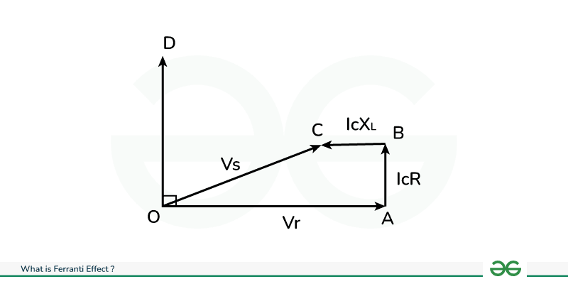
Phasor diagram of the given circuit is shown in below. During the Ferranti effect, there is no load subsequently
Receiving current Ir = 0
The receiving voltage Vr is taken as reference OA where the capacitive current Ic is addressed by opposite line OD driving the Vr by 90°. The capacitive current Ic has a voltage drop across the line resistance R and the line inductance L, as shown by the equation:
Voltage drop across the resistor = IcR = AB
Voltage drop across the inductor = IcXL = BC
The inductive voltage drop IcXL (BC) is 90 degrees higher than the resistive voltage drop IcR (AB). Where the sending voltage Vs is the amount of all voltage drops + receiving voltage represented by OC.
Vs = Vr + Resistive voltage drop + Inductive voltage drop
Vs = OA + AB + BC = OC
As shown in the phasor diagram, the receiving voltage Vr at the load side is grater than the sending voltage Vs at the source side.
Now let's derive the equation for the Ferranti effect using the same circuit diagram of the transmission line.
Vs = Vr + resistive drop + inductive drop
Vs = Vr + IcR + IcXL
Vs = Vr + Ic (R + XL)
Since capacitive current, Ic = jwCVr
Vs = Vr + jwCVr (R + XL)
Since XL = jwL
Vs = Vr + jwCVr (R + jwL)
Vs = Vr + jwCVrR + j 2w 2CLVr
Vs = Vr + jwCVrR - w 2CLVr
Vs - Vr = jwCVrR - w 2CLVr
In long transmission lines, the line resistance is a more smaller than the line reactance. Therefore the resistance R, as well as resistive voltage drop is neglected
Vs - Vr = - w 2CLVr
Now assume the capacitance and inductance per km of the length are Co and Lo respectively and the length of the transmission line is l. The equation becomes
Vs – Vr = -w2(CO I)(LO l)Vr
Vs – Vr = -w2 l 2 CoLoVr
Since the line capacitance is distributed throughout the entire length (l) of the transmission line, the charging current as well as the voltage drop associated with it is taken as an average.
Now assume Therefore;
Vs - Vr = - (1/2) w2 l 2 CoLoVr
The voltage distinction between the sending and receiving voltage is negative which implies the voltage rises. Additionally, it is directly proportional to the squares of line length (l) and frequency (w). This condition demonstrates that the Ferranti effect increases with an expansion in the length of the transmission line and supply frequency. Consequently little transmission lines and HVDC transmission are not impacted by the Ferranti effect.
The Ferranti effect in extensive transmission line where OE-signifies the receiving end voltage, OH-signifies the flow of current in the capacitor at the receiving end. A decrease in voltage across the resistance R is indicated by the FE-phasor, and a decrease in voltage across the inductance (X) is indicated by the FG. The OG-phasor means the sending end voltage in a condition of no-load. The nominal Pi model of the transmission line at no load condition circuit is shown in below.
In the following phasor representation, OE is greater than OG(OE>OG). In different terms, the voltage at the less than receiving end is better than the voltage at the transmitting end when the transmission line is at no load condition. Here the Ferranti effect phasor diagram is shown below.
Vs = (1+ZY/2)Vr + ZIr
Where, Ir =0 at no load condition
Vs = (1+ZY/2)Vr + Z (0)
= (1+ZY/2) Vr
Vs - Vr = (1+ZY/2)Vr-Vr
Vs - Vr = Vr [1+ZY/2-1]
Vs - Vr = (ZY/2) Vr
Z= (r + jwl)S, and Y = (jwc)S
Assuming that the transmission line's resistance is unnoticed
Vs - Vr = (ZY/2) Vr
Substitute Z= (r + jwl)S, and Y = (jwc)S in the above Vs
Vs - Vr= ½ ( jwls) (jwcs) Vr
Vs - Vr= - ½ (W2S2) lcVr
For the lines of above, 1/√LC = 3×10⁸m/s (velocity of electromagnetic wave transmission on the transmission lines).
1/√LC = 3×10⁸m/s
√LC = 1/3×108
LC = 1/(3×108 )2
Vs - VR = - ½ W2S2 . ( 1/(3×108 )2) Vr
W = 2πf
Vs - VR = - ((4π2/18)* 10-16) f2S2Vr
That's what the above equation represents (Vs - Vr) is negative, that means Vr is greater than Vs This is also illustrated that this effect will also determine by the electrical period of the transmission lines and frequency.
Generally, for each line
Vs = AVr + BLr
On no load condition
Ir =0, Vr = Vrnl
Versus = AVrnl
|Vrnl| = |Vs|/|A|
For a extensive transmission line, A is<1 and it reduces with the increase in the extent of the transmission line. Hence, the voltage at no load is more greater than the voltage at the load (Vrnl > Vs) As the length of line in the voltage on the collecting end, then at no load acts as the main.
Ferranti effect makes voltage instability in the electrical system that cause a dangerous hazardous for equipment and personnel at the load side. There are specific measures taken to limit the Ferranti effects.
The Ferranti effect arises when reactive power accumulates in the power system without loads to absorb it. We must install something that can absorb this excessive reactive power in the transmission line. This reactive power can be absorbed by installing a shunt reactor in the transmission line. Usually, it is installed in at the load end.
A medium transmission line requires the shunt reactor to be placed at the receiving end. However long transmission lines require it to be installed at a periodic distance or in the line. While underground cables have very high capacitance and require short distance of around 10 miles or 15 km intervals.
Ferranti effect happens when there is no or light load associated with the lines. To reduce the Ferranti effect, it should satisfy the given condition.
Load current > Charging current.
A transmission line's loads should be continuously monitored, and the load must be maintained above the limit. It tends to be finished by setting different light load lines onto a single line.
The following characteristics are shown below related to Ferranti effect :
Copper loss = I2 R
In conclusion, the Ferranti effect plays a vital role in the domain of electrical power systems, introducing the two difficulties and opportunities. Understanding this peculiarity is fundamental for power engineers and system operators to ensure the dependable and effective activity of transmission networks.
The Ferranti effect's favorable viewpoints lie in helping voltage regulation and reactive power management potential. When tackled appropriately, it can add to keeping up with reliable voltage levels, especially in regions served by lengthy transmission lines. This is significant for giving dependable capacity to distant districts and upgrading the general exhibition of the electrical systems.
Be that as it may, the Ferranti Impact additionally presents difficulties, especially as far as hardware stress, network shakiness, and dynamic circumstances. Uncontrolled voltage rise related with the Ferranti Impact can prompt mileage on electrical parts, network motions, and hardships in dealing with the impact under shifting load conditions. To losses the negative effects of the Ferranti Effect in practice, engineers use sophisticated methods like series compensation, shunt reactors, and voltage control devices. Finding some kind of harmony between utilizing its advantages and dealing with its difficulties is fundamental for ensuring the flexibility and soundness of modern day power systems.