 |
VOOZH | about |
|
VOOZH | about |
An electronic circuit called a filter circuit is made to either pass or block specific frequencies from an electrical signal. It is an essential part of many electrical systems and applications because it shapes a circuit's frequency response by blocking out undesired frequencies and letting in desired ones. Many electrical devices, including power supply, signal processing applications, audio systems, and communication systems, use filters.
Filters are circuits whose response is dependent on the input voltage's frequency. Many crucial tasks in a system can be carried out by filter circuits. While resistors, capacitors, and inductors can also be used to create filters, op-amps, resistors, and capacitors are the main components of most filter circuits.
In this article, we will be going through the Filter Circuit, We will start our Article with the definition of the Filter Circuit, Then we will go through its Components and Filter Design, Then we will go through its types and At last we will conclude our Article with its Characteristics, Advantages, Disadvantages and Some FAQs.
Table of Content
An electrical circuit that selectively permits some frequencies of an electrical signal to flow through while blocking others is called a filter circuit. It acts as a gatekeeper for frequencies, making sure that only those that are wanted reach the output. A filter circuit is used in a rectifier circuit to eliminate or filter out the AC components. A filter circuit is a device that permits the D.C. For successful implementation in a variety of electronic systems, a thorough comprehension of their guiding principles and meticulous evaluation of design parameters are essential. In a variety of electronic applications, filter circuits are essential for modifying and enhancing electrical signals.
The components of the rectified output to reach the load while removing the A.C. components from it. An LC filter circuit is a type of filter circuit that typically consists of an inductor (L) and a capacitor (C). An inductor only permits D.C. to flow, while a capacitor only permits A.C. to do so. Thus, the A.C. component of the rectified wave can be efficiently filtered out using an appropriate L and C network.
The components of a filter circuit are as follows:
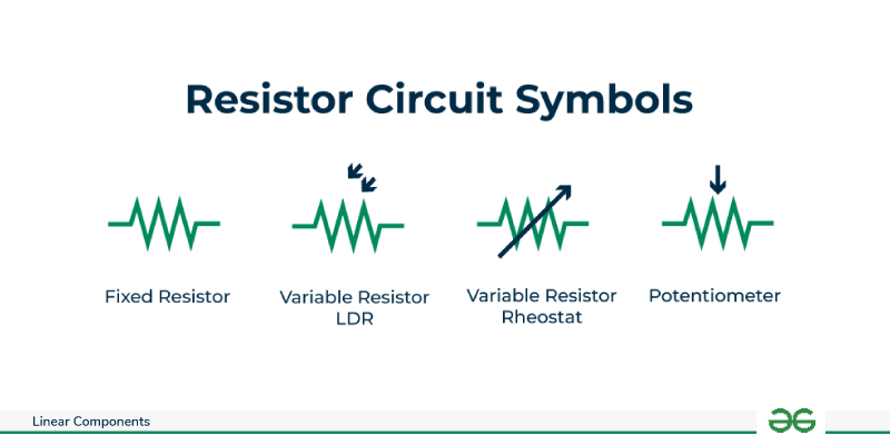
Function: The circuit's current flow is managed by a resistor. It is frequently used in filter circuits to set the time constants in conjunction with capacitors.
Symbol: The symbol of resistor is given below with its representations.
Symbol: The symbol of Capacitor is given below with its representations.
Function: Electrical energy is stored and released by capacitors. Capacitors are frequently employed in filter circuits to pass AC signals while blocking DC signals.
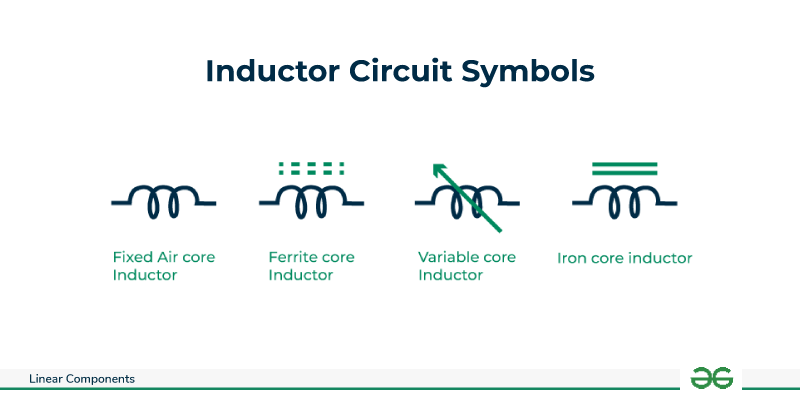
Symbol: The symbol of Inductor is given below with its representations.
Function: Inductors store energy in their magnetic fields and resist changes in current. They are frequently employed in filter circuits to allow high-frequency signals to be blocked and low-frequency signals to be passed.
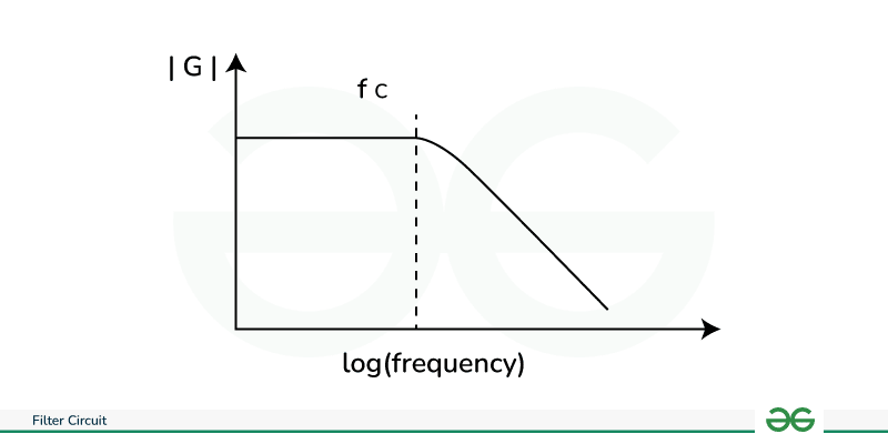
An electronic circuit known as a low-pass filter (LPF) attenuates signals higher than the cutoff frequency while permitting signals lower than the cutoff frequency to pass through. LPFs are frequently employed in electrical systems to ensure that only the intended low-frequency components reach the output by removing or reducing high-frequency noise, undesired harmonics, and interference.
Cutoff Frequency (fc): The cutoff frequency, often known as f c, is an important parameter that indicates when the filter starts to attenuate the input signal. While frequencies over the cutoff are gradually muted, frequencies below it are permitted to pass through with little attenuation. The cutoff frequency is measured in hertz (Hz) and is commonly represented as f c.
Filter Slope/Roll-off: The filter's roll-off, or how quickly it attenuates frequencies above the cutoff, is measured. Decibels per decade (dB/decade) or decibels per octave (dB/octave) are the units of measurement. The rate at which higher frequencies lose amplitude as they approach the cutoff frequency is determined by the slope.
An electronic circuit known as a high-pass filter (HPF) attenuates signals with frequencies lower than the cutoff frequency while permitting signals with frequencies greater than the cutoff frequency to pass through. High-pass filters (HPFs) are used in many electronic applications to emphasize a signal's high-frequency content and to remove or decrease undesired DC offsets and low-frequency components. The main elements and features of a high-pass filter are as follows:
Cutoff Frequency (fc): The frequency at which the filter starts to attenuate the input signal in an HPF is known as the cutoff frequency, just like in a Low-Pass Filter. While frequencies over the cutoff frequency pass through with little attenuation, those below it are gradually muted. The unit of measurement for the cutoff frequency (f c) is commonly hertz (Hz).
Filter Slope/Roll-off: The filter slope, sometimes referred to as roll-off, is the speed at which frequencies below the cutoff are attenuated. Decibels per decade (dB/decade) or decibels per octave (dB/octave) are the units of measurement. The slope controls the rate at which lower frequencies lose amplitude as they approach the cutoff frequency.
A Band-Pass Filter (BPF) is an electrical circuit that attenuates signals outside of the passband while permitting signals inside the passband to pass through. Two cutoff frequencies define the band-pass filter: a lower cutoff frequency (low f low ) as well as a higher cutoff frequency (high f high). The passband is formed by the frequencies that are passed with the least amount of attenuation between these two cutoff points. The main elements and features of a band-pass filter are as follows:
Center frequency: The geometric mean of the lower and higher cutoff frequencies determines the center frequency, which is the midway of the passband. Determining the core frequency at which the filter responds best is a critical parameter.
The bandwidth : The band-pass filter's bandwidth is the width of the frequency range within which signals can flow through with the least amount of attenuation. The difference between the upper and lower cutoff frequencies is how it is defined.
f high − f low BW = f equals ⁛ high − ⁰ low
Let some frequencies pass through while blocking others. It's helpful in removing interference from a particular frequency. Since power is the primary quantity of concern, the transfer function of a circuit is typically stated on a logarithmic scale in dB. A filter is characterized by :
Center frequency (f c): The midpoint of the lower and upper notch frequencies is the center frequency of a notch filter, just like in a band-pass filter. Determining the core frequency at which the filter responds best is a critical parameter.
Bandwidth (BW): The width of the frequency range in which signals are rejected or muted is the band-stop filter's bandwidth. It is described as the difference between the frequencies of the upper and lower notch:
f high − f low BW = f equals ⁛ high − ⁰ low
A digital processor is used by a digital filter to compute numerical values based on the signal's sampled values. A specialized DSP (Digital Signal Processor) chip or a general-purpose computer like a PC could be the processor. An ADC (analog to digital converter) must first be used to sample and digitize the analog input signal. The processor receives the generated binary numbers, which are successively sampled values of the input signal, and uses them to perform numerical calculations. Usually, the input numbers are multiplied by constants in these computations, and the products are then added. The filtered signal's sampled values, which are now the result of these calculations, are output through a DAC (digital to analog converter) if necessary to return the signal to analog form.
Basis for Comparison | Active Filter | Passive Filter |
|---|---|---|
Material | active parts like as transistors and op-amps | passive parts, such as capacitors, resistors, and inductors, etc. |
Cost | Expensive | cheap |
Circuit intricacy | More complex | Less complex |
Weight | Low Weight comparatively | bulkier since inductors are present. |
Q factor | high | very low |
Power Supply | required | not required |
In summary, filter circuits are essential for modifying the frequency response of electronic systems, giving engineers the ability to regulate and work with signals according to their frequency composition. There are four different types of filters: band-pass (BPF), high-pass (HPF), low-pass (LPF), and band-stop (BSF). Each kind has a specific use in a range of applications. Filter circuits are essential components of electronics that improve the effectiveness and caliber of signal processing for a variety of uses. For successful implementation in a variety of electronic systems, a thorough comprehension of their guiding principles and meticulous evaluation of design parameters are essential. In a variety of electronic applications, filter circuits are essential for modifying and enhancing electrical signals.