 |
VOOZH | about |
|
VOOZH | about |
A switching regulator is integrated into an electronic power supply called a switch-mode power supply (SMPS), which is sometimes referred to as a switcher, switched power supply, switching-mode power supply, or simply switcher. This power supply effectively converts electrical power. An SMPS, like other kinds of power supplies, converts current and voltage characteristics while transferring power from an AC or DC source (often mains power; see AC adapter) into DC loads, like a personal computer. Switched-mode energy sources can also be significantly lighter and more compact than linear power supplies since their transformers can be considerably smaller. This is due to the fact that, in contrast with the 50 to 60 Hz mains frequency, it works at a high rate of switching that extends from a few kHz to several MHz. The power supply architecture and the need for EMI (electromagnetic interference) suppression in commercial systems lead to a typically significantly higher component count and accompanying circuit complexity, despite the smaller transformer.
A switching regulator is included in an electronic power supply called a switched-mode power supply (SMPS) to facilitate effective electrical power conversion. An SMPS converts voltage and current while transferring power to DC loads via a DC or AC source, just like other suppliers.
Switching regulators are employed in SMPS devices to maintain & regulate the output voltage by turning on or off the load current. The mean value between on and off is the appropriate power output for a system. The SMPS reduces depletion strength because, in contrast to the linear power supply, it carries transistor switches between low dissipation, full-on as well as full-off phases and spends significantly fewer seconds in high dissipation cycles.
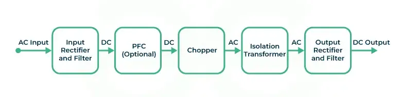
The input supply in this sort of SMPS is AC, and the output is DC. This AC power is converted to DC using rectifiers and filters. This erratic DC voltage is applied to the impacted circuits for power factor correction. This is due to a low current pulse that occurs near the voltage peak inside the rectifier.
This power source's input supply comes straight from a DC power source, which provides high-voltage DC power. Next, the frequency of this high-voltage DC power supply is lowered to 15KHz–5KHz. A 50 Hz steps-down transformer unit receives it after that. This transformer's output serves as the rectifier's input, and the rectifier's output provides the power that loads are drawn from. A closed-loop regulation is created when the oscillator is regulated on time. The transformer transfers its maximum power when its duty cycle is 50%. If its duty cycle is lowered, the transformer's power is likewise decreased by lowering the interruption.
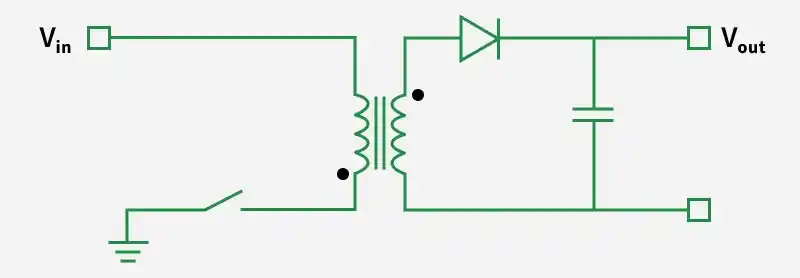
A fly-back converters SMPS is any SMPS with an output power of less than 100W. The circuit for these SMPS is easy to understand and less complicated than that of other SMPS. Low power consumption is the purpose of this kind of SMPS. Using a MOSFET, the unregulated voltage that is input of constant intensity switches at a frequency of about 100 kHz to the desired output voltage. A transformer is used to achieve voltage separation. A workable fly-back converter can be operated while the switch is controlled via PWM. Unlike a typical transformer, the fly-back transformer exhibits unique qualities. The two windings that make up the fly-back transformer function as magnetically coupled inductors. To improve filtering, capacitors and diodes are used to spread the transformer's output.
This kind of SMPS shares nearly the same design as the SMS flyback converter type. In order to control such SMPS, the switch is linked to the secondary winding that powers the transformer's output. The circuitry for filtering and correction is more intricate than that of a flyback converter. These SMPS, commonly referred to as DC-DC buck converters, are employed in transformer isolation and scaling applications.
For end users, these are some of the most well-known and widely utilized Switched Mode Power Supplies.
High-voltage DC power that is received from the AC mains has been rectified and filtered. After that, the high DC voltage is switched and sent to the primary side step-down transformer. The rectified & filtered output is gathered at the step-down transformer's secondary side before being supplied as the output into the power supply.
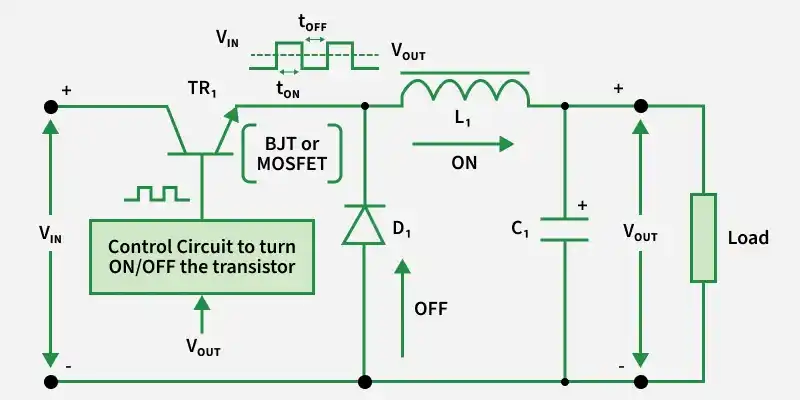
The choke in the forward converter transfers the current whether or not the transistor is conducting. To maintain the energy flow across the load during the transistor's off-time, the diode within the device conducts the current. Part of the electrical power is passed to the resultant load and stored by the choke during the On phase.
With a flyback converter, the inductor's magnetic field saves energy when the switch is turned on. Energy is released into the resulting voltage circuit when the toggle switch stays in the open position. The output voltage in a flyback converter determines its Duty cycle.
It is predicated on the Flyback theory. A current across the transformer primary begins to ramp up linear with the slope Vin/Lp during conduction. The quick recovery rectifier begins to function in reverse biassed and holds the conducting transistors ON as a result of the voltage that is induced in the secondary winding and feedback winding. When the current hits its maximum value, the core starts to saturate. As a result, the fixed base motor supported by input windings is unable to withstand a sudden increase in current. As a result, the switching starts to emerge from saturation.
An SMPS's great efficiency can be attributed to its constant input-to-output switching, which prevents extra power from being wasted as heat. The voltages in an SMPS circuit fluctuate continuously because it operates by switching. Either cutoff or saturation mode is used to run the switching device. The feedback circuitry's switching time regulates the output voltage. Duty cycle adjustments are made to change the switching time.