 |
VOOZH | about |
|
VOOZH | about |
In UML (Unified Modeling Language), a Collaboration Diagram is a type of Interaction Diagram that visualizes the interactions and relationships between objects in a system. It shows how objects collaborate to achieve a specific task or behavior. Collaboration diagrams are used to model the dynamic behavior of a system and illustrate the flow of messages between objects during a particular scenario or use case.
Table of Content
A collaboration diagram is a behavioral UML diagram which is also referred to as a communication diagram. It illustrates how objects or components interact with each other to achieve specific tasks or scenarios within a system.
In simpler terms, they visually represents the interactions between objects or components in a system and show how they collaborate to accomplish tasks within a system, and also illustrate the system's object architecture.
Collaboration diagrams is important for understanding communication, design, analysis, and documentation of the system's architecture and behavior.
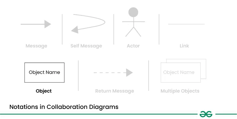
There are several components in Collaboration Diagram. Let's see those components and their notations:
Objects are represented by rectangles with the object's name at the top. Each object participating in the interaction is shown as a separate rectangle in the diagram. Objects are connected by lines to indicate messages being passed between them.
Multiple objects are represented by rectangles,each with the object's name inside, and interactions between them are shown using arrows to indicate message flows.
They are usually shown at the top or side of the diagram. Actors indicate their involvement in the interactions with the system's objects or components. They are connected to objects through messages, showing the communication with the system.
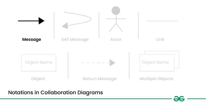
Messages represent communication between objects. Messages are shown as arrows between objects, indicating the flow of communication. Each message may include a label indicating the type of message (e.g., method call, signal). Messages can be asynchronous (indicated by a dashed arrow) or synchronous (solid arrow).
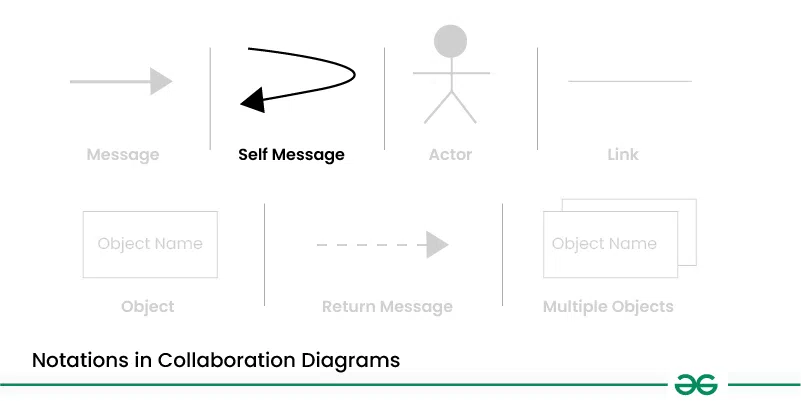
This is a message that an object sends to itself. It represents an action or behavior that the object performs internally without involving any other objects. Self-messages are useful for modeling scenarios where an object triggers its own methods or processes.
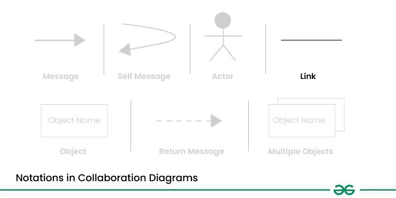
Links represent associations or relationships between objects. Links are shown as lines connecting objects, with optional labels to indicate the nature of the relationship. Links can be uni-directional or bi-directional, depending on the nature of the association.
Return messages represent the return value of a message. They are shown as dashed arrows with a label indicating the return value. Return messages are used to indicate that a message has been processed and a response is being sent back to the calling object.
Below are the steps to draw collaboration diagrams:
Below are the main use cases of collaboration diagrams:
Let's understand collaboration diagram using the example of Job Recruitment System.
The recruiter object interacts with the database object to verify the login, check the jobs, select a talented applicant, and send interview details.
This object represents a job candidate applying for a position. The Applicant interacts with the Recruiter to share personal and professional information and participate in the interview. After the interview, the Recruiter selects the promising candidate and sends a joining letter to the Applicant.
Applicant --attend test --> Database
Applicant --provide details --> Database
This object represents the person or system responsible for hiring new employees. The Recruiter interacts with the Applicant to verify login details, check available job positions, select suitable candidates, send interview information, and issue joining letters. The Recruiter also works with the Database to retrieve and update necessary information.
Recruiter --verify login--> Database
Recruiter <-- confirms login --> Database
Recruiter --check jobs positions --> Database
Recruiter --select talented applicant --> Applicant
Recruiter --send interview details --> Applicant
Recruiter --send joining letter --> Applicant
This object represents the system that stores important information for the recruitment process. The Database interacts with the Recruiter to provide job positions, verify logins, and send details about applicants. It also interacts with the Applicant to store and retrieve necessary information about them.
Database --send jobs --> Recruiter
Collaboration diagrams in UML are often used in the early stages of software development to:
Below are the benefits of collaboration diagram:
Below are the challenges of Collaboration Diagram:
.webp)