 |
VOOZH | about |
|
VOOZH | about |
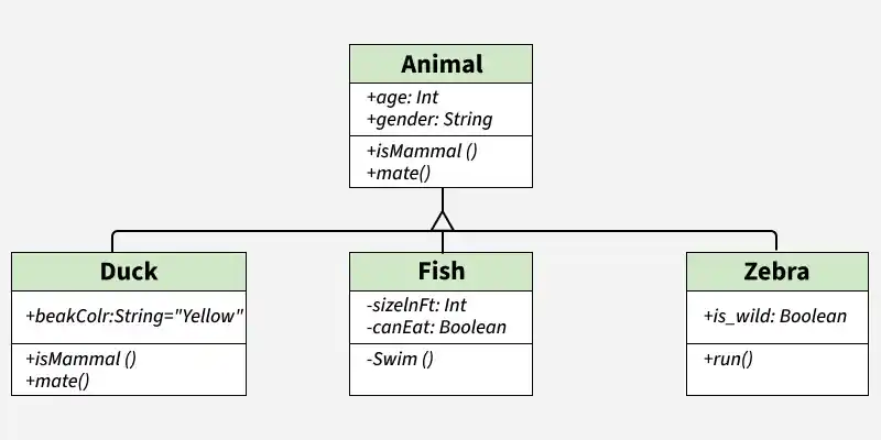
A UML class diagram shows the structure of a system by displaying its classes, their attributes, methods, and the relationships between them. It helps the team understand how the system is organized and how components interact.
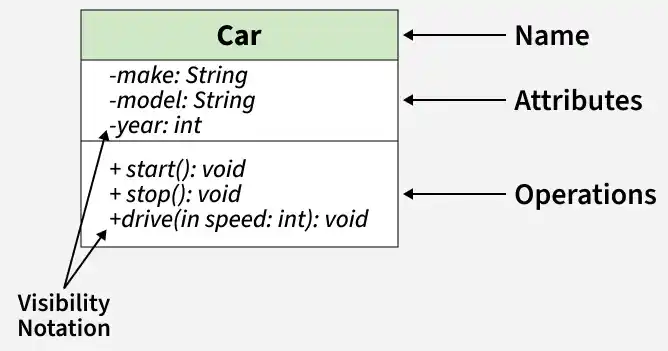
Classes are depicted as boxes, each containing three compartments for the class name, attributes, and methods.
Visibility notations indicate the access level of attributes and methods. Common visibility notations include:
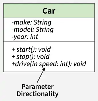
+ for public (visible to all classes)- for private (visible only within the class)# for protected (visible to subclasses)~ for package or default visibility (visible to classes in the same package)There are three main parameter directionality notations used in class diagrams:
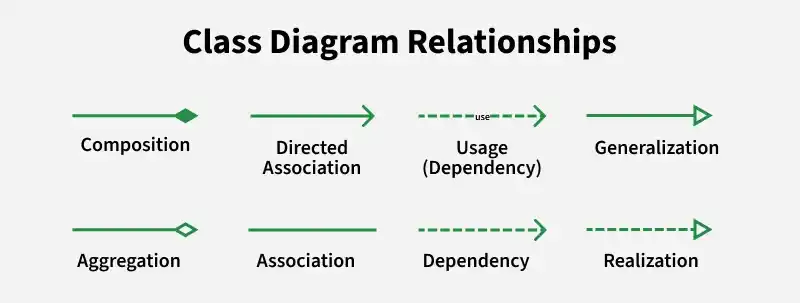
In class diagrams, relationships between classes describe how classes are connected or interact with each other within a system. Here are some common types of relationships in class diagrams:
An association represents a bi-directional relationship between two classes. It indicates that instances of one class are connected to instances of another class. Associations are typically depicted as a solid line connecting the classes, with optional arrows indicating the direction of the relationship.
A directed association in a UML class diagram represents a relationship between two classes where the association has a direction, indicating that one class is associated with another in a specific way.
Aggregation is a specialized form of association that represents a "whole-part" relationship. It denotes a stronger relationship where one class (the whole) contains or is composed of another class (the part). Aggregation is represented by a diamond shape on the side of the whole class. In this kind of relationship, the child class can exist independently of its parent class.
Composition is a stronger form of aggregation, indicating a more significant ownership or dependency relationship. In composition, the part class cannot exist independently of the whole class. Composition is represented by a filled diamond shape on the side of the whole class.
Inheritance represents an "is-a" relationship between classes, where one class (the subclass or child) inherits the properties and behaviors of another class (the superclass or parent). Inheritance is depicted by a solid line with a closed, hollow arrowhead pointing from the subclass to the superclass.
Realization indicates that a class implements the features of an interface. It is often used in cases where a class realizes the operations defined by an interface. Realization is depicted by a dashed line with an open arrowhead pointing from the implementing class to the interface.
A dependency exists between two classes when one class relies on another, but the relationship is not as strong as association or inheritance. It represents a more loosely coupled connection between classes.
A usage dependency relationship in a UML class diagram indicates that one class (the client) utilizes or depends on another class (the supplier) to perform certain tasks or access certain functionality. The client class relies on the services provided by the supplier class but does not own or create instances of it.
UML Class Diagrams provide several benefits that help developers design, analyze, and manage software systems more effectively.
UML Class Diagrams are widely used in software development to represent system structure and object-oriented designs.