 |
VOOZH | about |
|
VOOZH | about |
In a computer, most of the electronic circuits are made up logic gates. Logic gates are used to create a circuit that performs calculations, data storage or shows off object-oriented programming especially the power of inheritance. Logic gates can also be constructed using vacuum tubes, electromagnetic elements like optics, molecule etc.
A Logic gate is an elementary building block of any digital circuits. It takes one or two inputs and produces output based on those inputs. Outputs may be high (1) or low (0). Logic gates are implemented using diodes or transistors. There are seven basic logic gates defined, these are:
Below are the brief details about them along with their implementation:
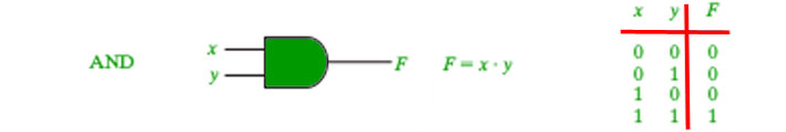
The AND gate gives an output of 1 if both the two inputs are 1, it gives 0 otherwise. 👁 Image
Below are the programs to implement AND gate using various methods:
 1 AND 0 = 0
 0 AND 1 = 0
 1 AND 1 = 1
 0 AND 0 = 0
 1 AND 0 = 0
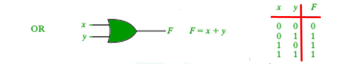
The OR gate gives an output of 1 if either of the two inputs are 1, it gives 0 otherwise. 👁 Image
Below are the programs to implement AND gate using various methods:
 1 AND 0 = 1
 0 AND 1 = 1
 1 AND 1 = 1
 0 AND 0 = 0
 1 AND 0 = 1
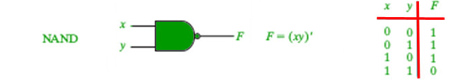
The NAND gate (negated AND) gives an output of 0 if both inputs are 1, it gives 1 otherwise. 👁 Image
Below are the programs to implement NAND gate using various methods:
 1 NAND 0 = 1
 0 NAND 1 = 1
 1 NAND 1 = 0
 0 NAND 0 = 1
 1 NAND 0 = 1
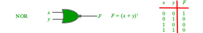
The NOR gate (negated OR) gives an output of 1 if both inputs are 0, it gives 1 otherwise. 👁 Image
Below are the programs to implement NOR gate using various methods:
 1 NOR 0 = 0
 0 NOR 1 = 0
 1 NOR 1 = 0
 0 NOR 0 = 1
 1 NOR 0 = 0
It acts as an inverter. It takes only one input. If the input is given as 1, it will invert the result as 0 and vice-versa. 👁 Image
Below are the programs to implement NOT gate using various methods:
 NOT 1 = 0
 NOT 0 = 1
 NOT 1 = 0
 NOT 0 = 1
 NOT 1 = 0
Logic gates are basic building components of digital circuits necessary to design complex systems. They are used to perform logical operations. It is important to understanding the working and combination of these gates in order to design circuits that perform tasks correctly and efficiently. Logic gates can help develop a solid foundation in digital electronics and pave the way for exploring more advanced topics.