 |
VOOZH | about |
|
VOOZH | about |
In Boolean Algebra, there are three basic operations, which are analogous to disjunction, conjunction, and negation in propositional logic . Each of these operations has a corresponding logic gate. Apart from these, there are a few other logic gates as well. It was invented by George Boole.
A gate can be defined as a digital circuit that can allow a signal (electric current) to pass or stop. A type of gate that allows a signal to pass through when certain logical conditions are met. Different logic gates have different logical conditions.
Truth Table: A truth table is a table that shows all possible combinations of inputs and outputs for a logic gate.
Given Below are the different types of Logic Gates :
The AND gate gives an output of 1 when if both the two inputs are 1, it gives 0 otherwise. For n-input gate if all the inputs are 1 then 1 otherwise 0.The AND gate operation is similar to the standard multiplication of 1s and 0s.The (.) dot represents the AND operation.
The Expression for AND gate can be given as
X=(A.B)
Where,
X is the output of gate
A and B are the inputs of the gate
The OR gate gives an output of 1 if either of the two inputs are 1, it gives 0 otherwise. For n-input gate if all the inputs are 0 then 0 otherwise 1.The OR Operation is represented by the +.
The Expression for OR Gate is given as
X=A+B
Where,
X is the output of gate
A and B are the inputs of the gate
The NOT gate gives an output of 1 if the input is 0 and vice-versa. It is also known as Inverters. In Boolean algebra NOT operation is represented by bar over the variable such as .
The Expression for NOT Gate can be given as
Where,
X is the output of gate
A is the inputs of the gate
The XOR gate gives an output of 1 if either both inputs are different, it gives 0 if they are same. For n-input gate if the number of input 1 are odd then it gives 1 otherwise 0.For a two-input XOR gate it means that the output is true only if exactly one of the inputs is true.
The Expression for XOR Gate can be given as
X = A’B + AB’
Where,
X is the output
A and B are the inputs
Thus we need 5 NOR GATE to implement XOR GATE.
The NAND gate (negated AND) gives an output of 0 if both inputs are 1, it gives 1 otherwise. For n-input gate if all inputs are 1 then it gives 0 otherwise 1.The Term "NAND" can be said as "Not AND".
The Expression for NAND Gate can be given as
Where,
Y is the Output of gate
A and B is the input of gate
The NOR gate (negated OR) gives an output of 1 only if both inputs are 0, it gives 0 otherwise. For n-input gate if all inputs are 0 then it gives 1 otherwise 0.The "NOR" can be said as "NOT OR".
The Expression for NOR Gate can be given as
Where,
Y is the Output of gate
A and B is the input of gate
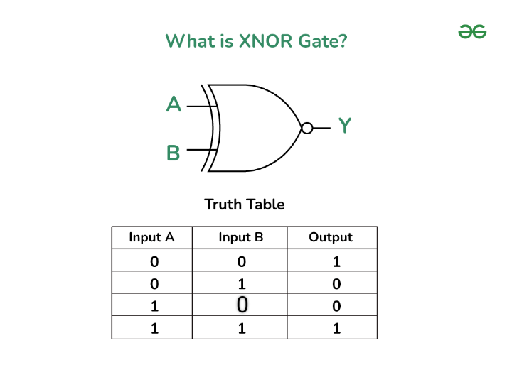
The XNOR gate (negated XOR) gives an output of 1 if both inputs are same and 0 if they are different. For n-input gate if the number of input 1 are even then it gives 1 otherwise 0 or if the number of input 0 is even then the output is 1, otherwise 0'. The "XNOR" can be said as "Exclusive NOR".
The Expression for XNOR Gate can be given as
Y=A⊙B
Where,
Y is the Output of gate
A and B is the input of gate
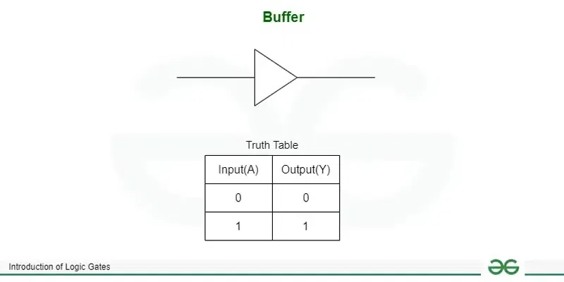
A Buffer Gate is a digital logic gate that amplifies a signal. It doesn't change the logic state (it outputs exactly what is input), but its primary purpose is to ensure that the signal can drive more circuits without weakening. Essentially, a buffer isolates the input from the output, making the output more robust.
Buffers are often used when a signal needs to drive a large number of other gates or when it needs to travel over a long distance without losing strength.
The Expression for Buffer can be given as
Y=A
Where,
Y is the Output of gate
A is the input of gate
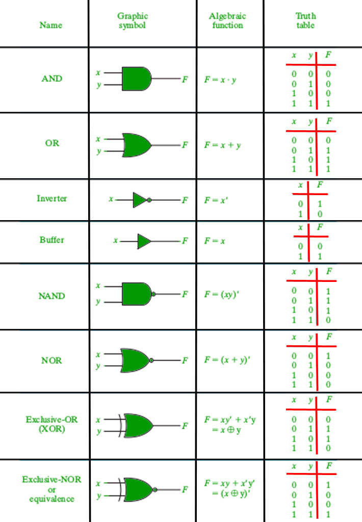
Every Logic gate has a graphical representation or symbol associated with it. Below is an image which shows the graphical symbols and truth tables associated with each logic gate. 👁 Image
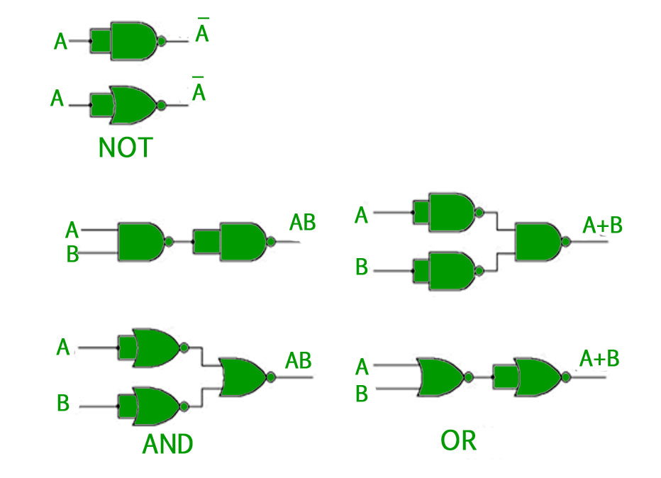
Out of the eight logic gates discussed above, NAND and NOR are also known as universal gates since they can be used to implement any digital circuit without using any other gate. This means that every gate can be created by NAND or NOR gates only. Implementation of three basic gates using NAND and NOR gates is shown below - 👁 Image
Implemented Using NAND
The Implementation of NAND Gates are
Implemented using NOR
The Implementation of NOR Gate are
Given Below are the Applications of logic gates
Despite their numerous advantages, logic gates have their disadvantages. The following paragraphs discuss some shortcomings of logic gates.
In this Article we have gone through Logic Gates, we have seen different types of logic gates with their logical diagrams and truth table, we have also gone through the implementation of Nor and Nand gate and we have seen the applications of the logical gates.