 |
VOOZH | about |
|
VOOZH | about |
NOR gate performs NOR(NOT OR) operation between two or more binary inputs and gives output binary signal. This is a combination of OR gate and NOT gate. It gives the output high(1) only when all of its inputs are low(0). In simple words we can say that NOR gate is the opposite (inverted) of OR Gate. It is also known as the Universal Gate because it can be used to implement other basic logic gates like AND, OR, and NOT gate by connecting NOR gates in specific configurations.
The Boolean expression for the NOR gate is the complement of logical multiplication of inputs which is given(denoted) by plus sign as
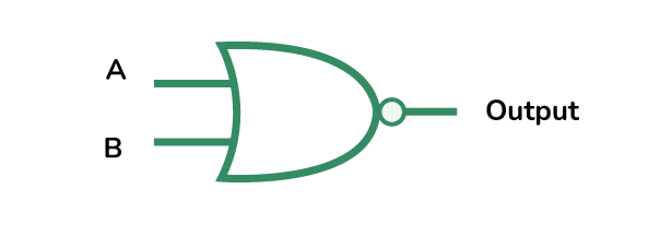
O = (A + B)'
Below is the symbolic representation of NOR Gate.
👁 NOR GATE SymbolAccording to its behavior :
Returns 1, if all the inputs are 0
Returns 0, if any of the input is 1, or all of the inputs are 1.
There are basically three types of NOR gate, based on the number of inputs:
It is the simple form of NOR gate. In this type of NOR gate, there are only two input values and one output values. There are total of 22=4 combinations of inputs possible. The logic design and Truth table are mentioned below.
👁 NOR GateUnlike the 2 input NOR gate has two inputs, the 3-inputs NOR gate has total of three inputs. The NOR gate can be joined(cascaded) together to form individual inputs of any number. There are total of 23=8 combinations of inputs possible. The Boolean expression of NOR gate is defined as binary operation addition(+).
👁 3-Input-NOR-GateWe can form NOR gate with any number of inputs i.e., n inputs. The output is high(1) only when all the inputs are false (0). If any one or more of the inputs are high(1), the output will be low(0). There are total of 2n combinations of inputs possible. When there is NOR gate with multiple inputs but you don't need to use all of them (example, you have a 5-input NOR gate, but only need 4 inputs) , then the unused input should be handled properly to avoid affecting the output.
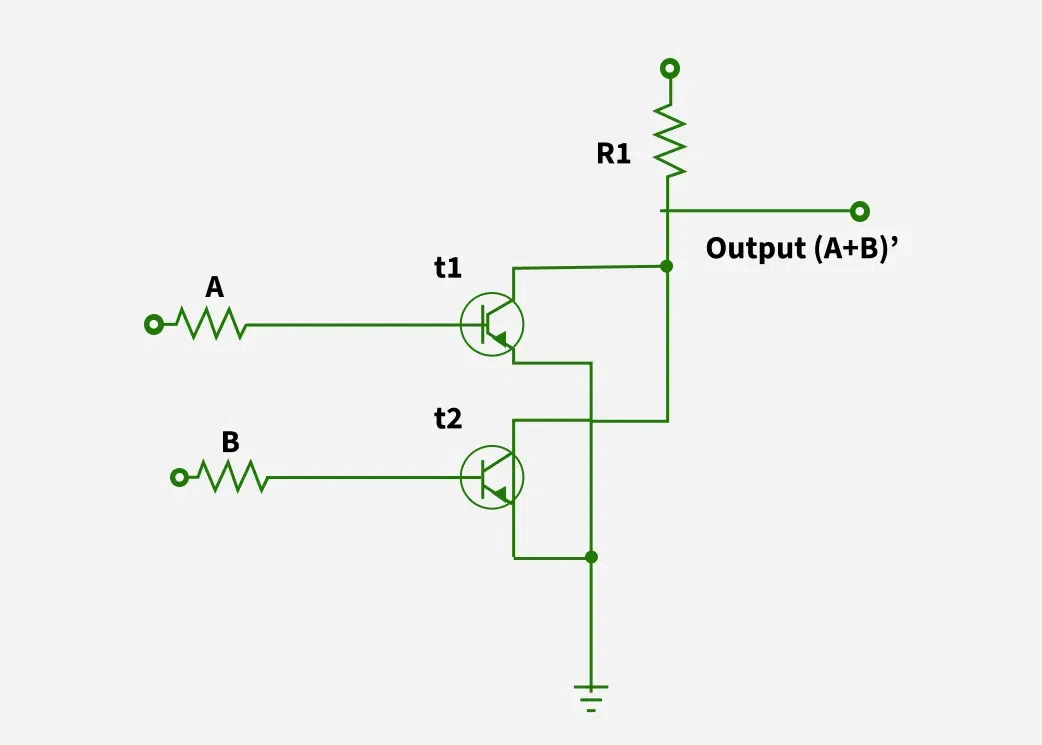
👁 4-Input-Nor-GateNOR gate can be constructed using transistors, which are the key blocks of digital electronics. In this transistors acts as a small switches in a circuit, turning on or off based on the signal received from the input. In NOR gate, transistors is used to make sure that the output is high(1) only when all of its inputs are low(0). NOR gate can be implemented by using transistor in various ways, but two transistor method is the most common method.
👁 nor-gate-in-terms-of-TransistorIn a transistor-based NOR gate, two or more NPN transistors are connected side by side(in parallel). The Key concept here is that for the output to be high (1), all the transistors must be off. This means that each input must provide the required signal to turn off its corresponding transistor.
- When both inputs (A and B) are low (0), neither transistor is turned on, so no current flows from the output to ground. The pull-up resistor keeps the output at a high (1) state. This results in a high output.
- When either input is high (1), the corresponding transistor turns on. This provides a path for current to flow from the output to ground, pulling the output down to low (0). If both inputs are high (1), both transistors turn on, and the output is also pulled low (0).