 |
VOOZH | about |
|
VOOZH | about |
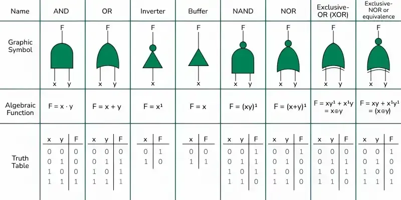
Logic gates are the fundamental building blocks in digital electronics.
Logic gates can be broadly classified into three main categories :
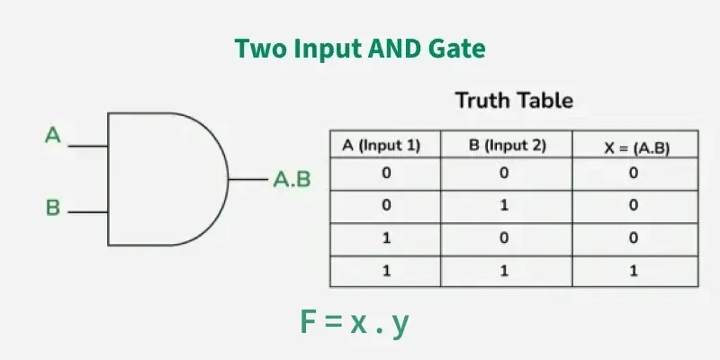
An AND gate is used to perform logical Multiplication of binary input. The Output state of the AND gate will be high (1) if both the input is high (1), else the output state will be low(0) if any of the input is low (0).
The Boolean Expression or logic for the AND gate is the logical multiplication of inputs denoted by a full stop or single dot as :
X = A.B
The value of X will be True when both the inputs will be True.
The following are two main properties of the AND gate:
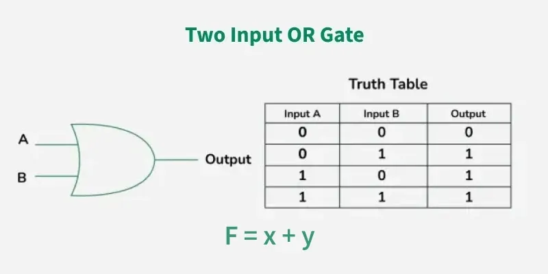
OR GATE is most widely used digital logic circuit. The output state of OR gate will be high i.e., (1) if any of the input state is high or 1, else output state will be low i.e., 0.
The Boolean Expression for the OR gate is the logical addition of inputs denoted by plus sign (+) as
X= A+B
The value of X will be high(true) when one of the inputs is set to high (true).
An OR gate have the following two properties:
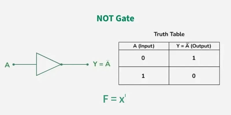
In digital electronics, the NOT gate is one of the basic Logic Gate having only a single input and a single output. It is also known as inverter or inverting buffer. When the input signal is "low" the output signal is "high" and vice-versa.
The Boolean expression of NOT Gate is as follows
Y = Ā or
Y = A’
the value of Y will be high when A will be low.
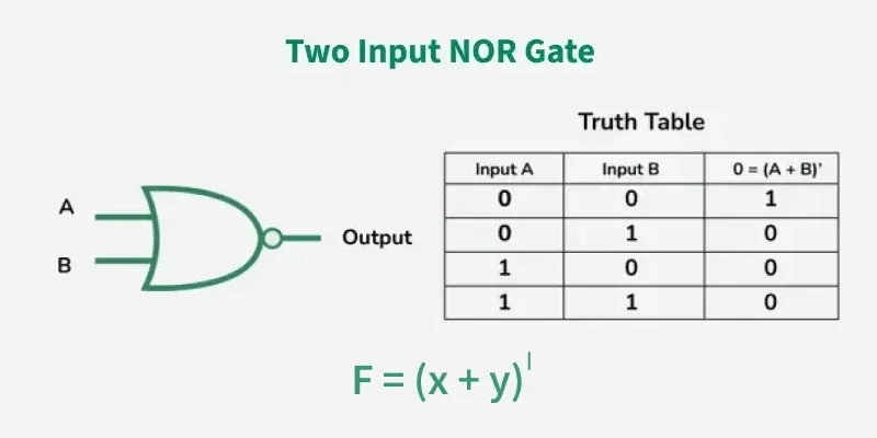
The NOR gate is the type of universal logic gate. It takes two or more inputs and gives only one output. The output state of the NOR gate will be high (1) when all the inputs are low (0). NOR gate returns the complement result of the OR gate. It is basically a combination of two basic logic gates i.e., OR gate and NOT gate.
The Boolean expression of NOR gate is as follows:
If A and B are considered as two inputs, and O as output, then the expression for a two input NOR gate will be
O = (A + B)’
The value of O will be true when all of its inputs are set to 0.
The following are two important properties of NOR gate:
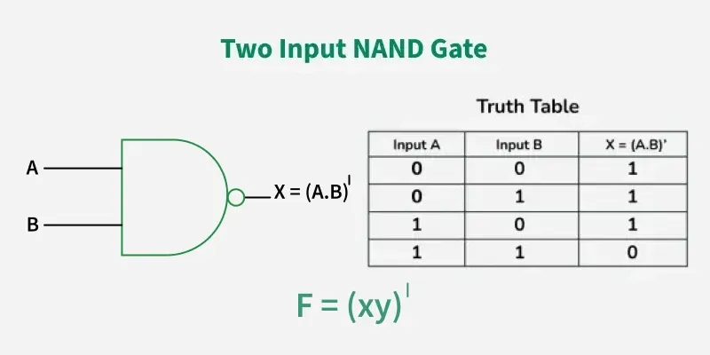
The NAND Gate is another type of Universal logic gate. The NAND gate or "Not AND" is the combination of two basic logic gates AND gate and the NOT gate connected in series. It takes two or more inputs and gives only one output. The output of the NAND gate will give result high (1) when either of its input is high (1) or both of its input are low (0). In simple, it performs the inverted operation of AND gate.
The Boolean Expression of NAND Gate is as follows
Say we have two inputs, A and B and the output is called X, then the expression is
X = (A. B)’
The following are the two key properties of NAND Gate
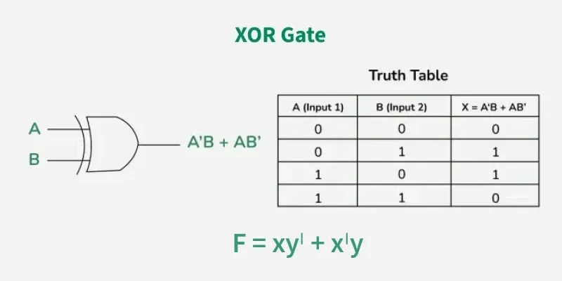
In digital electronics, there is a specially designed logic gate named, XOR gate, which is used in digital circuits to perform modulo sum. It is also referred to as Exclusive OR gate or Ex-OR gate. it is used extensively in arithmetic logic circuits., logic comparators and error detection circuits. The XOR gate can take only two inputs at a time and give an output. The output of the XOR gate is high (1) only when its two inputs are dissimilar i.e., if one of them is low (0) then other one will be high (1).
Say we have two inputs, A and B and the output is called X, then the expression is
The Boolean expression of XOR Gate is as follows
X = A’B + AB’
The following two are the main properties of the XOR gate:
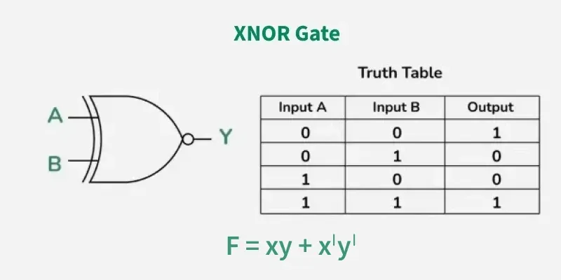
The XNOR is the combination of XOR gate and NOT gate. The output of the XNOR gate is high(1) when both the inputs are high (1) or low(0). In other words, the output of the XNOR gate is high(1) when both the inputs are the same. the XNOR gate can sometimes be called as Equivalence gate. In simple words, The XNOR gate is the complement of the XOR gate.
The following is the Boolean expression of the XNOR gate,
Y = A ⊙ B
Here, A and B are the input variables and Y is the output variable.
This expression can also be written as follows,
Y = AB + A’B’
We can also express the operation of an XNOR gate using XOR gate logic as follows:
Y = (A ⊕ B)’
The following are two key properties of XNOR gate:
Logic gates are the fundamental building blocks of all digital circuits and devices like computers. Here are some key digital devices in which logic gates are utilized to design their circuits.
Here are some devices, where logic gates is used;