 |
VOOZH | about |
|
VOOZH | about |
A multiplexer is a combinational circuit that has many data inputs and a single output, depending on control or select inputs. For N input lines, log2(N) selection lines are required, or equivalently, for 2n input lines, n selection lines are needed.
The Mux can be of different types based on input but in this article, we will go through two major types of mux, which are
The 2x1 is a fundamental circuit which is also known 2-to-1 multiplexer that are used to choose one signal from two inputs and transmits it to the output. The 2x1 mux has two input lines, one output line, and a single selection line. It has various applications in digital systems such as in microprocessor it is used to select between two different data sources or between two different instructions.
Given Below is the Block Diagram and Truth Table of 2:1 Mux. In this Block Diagram where I0 and I1 are the input lines, Y is the output line and S0 is a single select line.
The output of the 2x1 Mux will depend on the selection line S0,
Using the Truth Table ,the Logical Expression for Mux can be determined as
Using truth table the circuit diagram can be given as
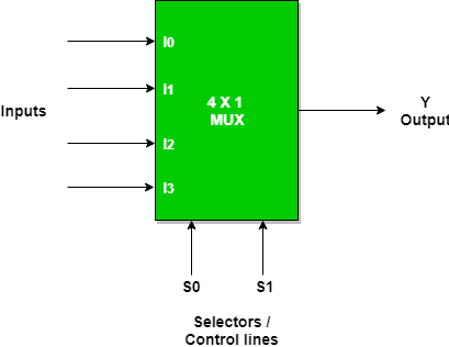
The 4x1 Multiplexer which is also known as the 4-to-1 multiplexer. It is a multiplexer that has 4 inputs and a single output. The Output is selected as one of the 4 inputs which is based on the selection inputs. The number of the Selection lines will depend on the number of the input which is determined by the equation ,In 4x1 Mux the selection lines can be determined as ,slo two selections are needed.
In the Given Block Diagram I0, I1, I2, and I3 are the 4 inputs and Y is the Single output which is based on Select lines S0 and S1.
👁 4:1 Multiplexer
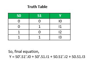
The output of the multiplexer is determined by the binary value of the selection lines
Given Below is the Truth Table of 4x1 Multiplexer
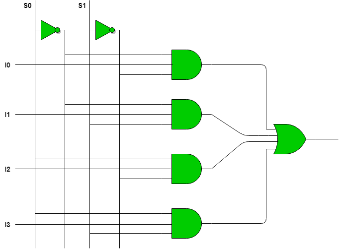
Using truth table the circuit diagram can be given as
👁 Circuit Diagram of 4:1 Multiplexers
Multiplexer can act as universal combinational circuit. All the standard logic gates can be implemented with multiplexers.
Given below are the Implementation of Different gate using 2:1 Mux
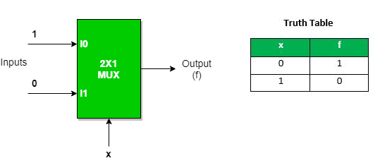
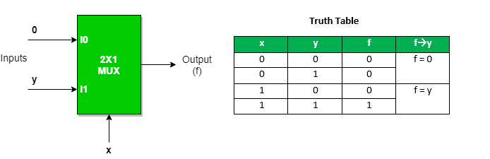
The Not gate from 2:1 Mux can be obtained by
Given Below is the Diagram for the Logical Representation of NOT gate using 2 : 1 Mux
👁 Implementation of NOT gate using 2 : 1 Mux
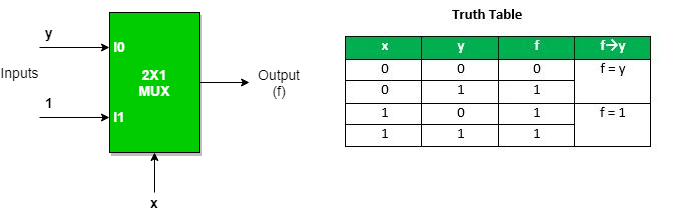
The And gate from 2:1 Mux can be obtained by
Given Below is the Diagram for the Logical Representation of AND gate using 2 : 1 Mux
👁 Implementation of AND gate using 2 : 1 MuxFor further more on the Implementation of AND gate using 2 : 1 Mux
The OR gate from 2:1 Mux can be obtained by
Given Below is the Diagram for the Logical Representation of OR gate using 2 : 1 Mux
👁 Implementation of OR gate using 2 : 1 Mux
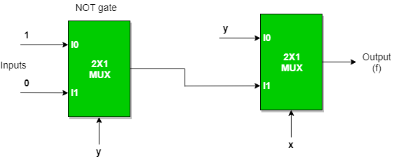
Implementation of NAND, NOR, XOR and XNOR gates requires two 2:1 Mux. First multiplexer will act as NOT gate which will provide complemented input to the second multiplexer.
The NAND gate from 2:1 Mux can be obtained by
Given Below is the Diagram for the Logical Representation of NAND gate using 2 : 1 Mux
👁 Implementation of NAND gate using 2 : 1 Mux
For further more on the Implementation of NAND gate using 2 : 1 Mux
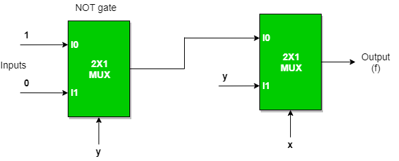
The Nor gate from 2:1 Mux can be obtained by
Given Below is the Diagram for the Logical Representation of NOR gate using 2 : 1 Mux
👁 Implementation of NOR gate using 2 : 1 Mux
For further more on the Implementation of NOR gate using 2 : 1 Mux
The Nor gate from 2:1 Mux can be obtained by
Given Below is the Diagram for the Logical Representation of EX-OR gate using 2 : 1 Mux
👁 Implementation of EX-OR gate using 2 : 1 Mux
Given Below is the Diagram for the Logical Representation of EX-OR gate using 2 : 1 Mux
The Nor gate from 2:1 Mux can be obtained by
👁 Implementation of EX-NOR gate using 2 : 1 Mux
Given Below are the Implementation of Higher Order MUX Using Lower Order MUX
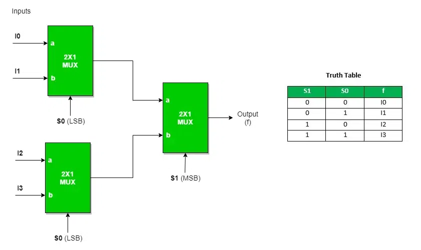
Three 2: 1 MUX are required to implement 4 : 1 MUX.
Similarly,
While an 8:1 MUX requires seven (7) 2:1 MUX, a 16:1 MUX requires fifteen (15) 2:1 MUX, and a 64:1 MUX requires sixty-three (63) 2:1 MUX. Hence, we can draw the conclusion that an MUX requires sixty-three (63) 2:1 MUX. Hence, we can draw the conclusion that an 2 n :1 MUX requires (2n−1)2:1 MUX (2 n −1)2:1 MUX.
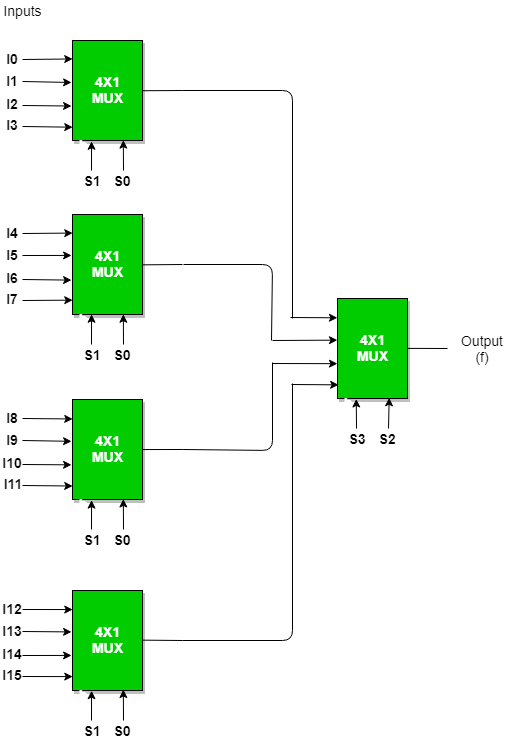
Given Below is the logical Diagram of 16:1 Mux Using 4:1 Mux
In general, to implement B : 1 MUX using A : 1 MUX , one formula is used to implement the same.
B / A = K1,
K1/ A = K2,
K2/ A = K3
KN-1 / A = KN = 1 (till we obtain 1 count of MUX).
And then add all the numbers of MUXes = K1 + K2 + K3 + .... + K N .
To implement 64 : 1 MUX using 4 : 1 MUX
Using the above formula, we can obtain the same.
64 / 4 = 16
16 / 4 = 4
4 / 4 = 1 (till we obtain 1 count of MUX)
Hence, total number of 4 : 1 MUX are required to implement 64 : 1 MUX = 16 + 4 + 1 = 21.
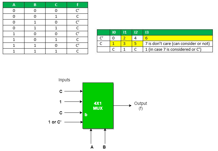
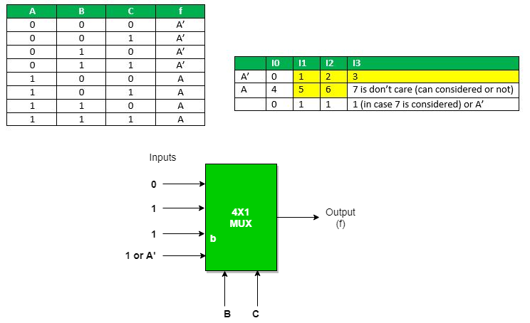
f(A, B, C) = (1, 2, 3, 5, 6) with don't care (7)
Using A and B as the select lines for 4 : 1 MUX,
AB as select: Expanding the minterms to its boolean form and will see its 0 or 1 value in Cth place so that they can be placed in that manner.
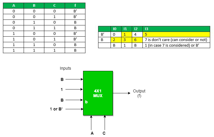
AC as select : Expanding the minterms to its Boolean form and will see its 0 or 1 value in Bth place so that they can be place in that manner.
👁 AC as select
BC as select: Expanding the minterms to its boolean form and will see its 0 or 1 value in A th place so that they can be place in that manner.
➣ Also Check - Demultiplexer(DEMUX)
.png)
.webp)