 |
VOOZH | about |
|
VOOZH | about |
In this article, we will go through Code Converters - Binary to/from Gray Code, we will start our article by defining Code converters, Binary code and Gray code, and then we will go through the conversion of binary code to gray code and vice versa.
Code Converters are the digital circuits or algorithms that are designed to translate data representation from one format to the other format. In this article, we will go through binary to gray code converters. The binary-to-Gray code converter takes binary input and translates it to its corresponding gray code representation.
For more about conversions please go through Number System and base conversions.
The Binary code is the numerical system used in digital electronics. It only consists of two Symbols which are 0 and 1. In binary code each digit is represented by power of 2 with the starting bit (right most bit) as 20 and bit as 21 and so on. The binary code is serves as the basis for encoding text, number and various other types of data in the digital devices.
Gray Code system is a binary number system in which every successive pair of numbers differs by only one bit. It is used in applications in which the normal sequence of binary numbers generated by the hardware, is read while the system changes from the initial state to the final state. This could have serious consequences for the machine using the information. The Gray code eliminates this problem since only one bit changes its value during any transition between two numbers.
Another Name of Gray Code
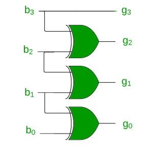
Let b0, b1, b2 and b3 be the bits representing the binary numbers, where b0 is the LSB and b3 is the MSB, and Let g0, g1, g2, and g3 be the bits representing the gray code of the binary numbers, where g0 is the LSB and g3 is the MSB.
The truth table for the conversion is
| Binary (B3 B2 B1 B0) | Gray Code (G3 G2 G1 G0) |
|---|---|
| 0000 | 0000 |
| 0001 | 0001 |
| 0010 | 0011 |
| 0011 | 0010 |
| 0100 | 0110 |
| 0101 | 0111 |
| 0110 | 0101 |
| 0111 | 0100 |
| 1000 | 1100 |
| 1001 | 1101 |
| 1010 | 1111 |
| 1011 | 1110 |
| 1100 | 1010 |
| 1101 | 1011 |
| 1110 | 1001 |
| 1111 | 1000 |
To find the corresponding digital circuit, we will use the K-Map technique for each of the gray code bits as output with all of the binary bits as input.
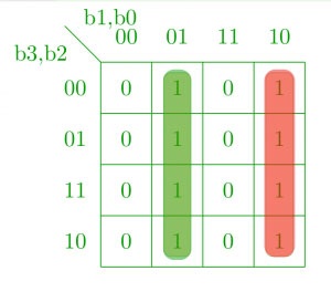
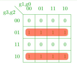
K-map for g0:
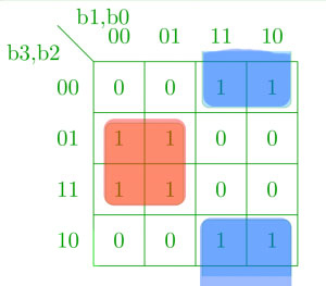
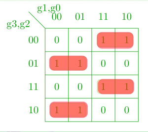
👁 ImageK-map for g1:
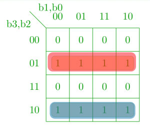
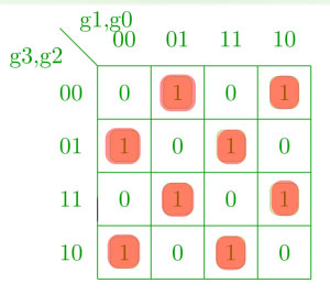
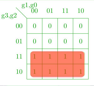
👁 ImageK-map for g2:
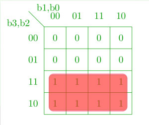
👁 ImageK-map for g3:
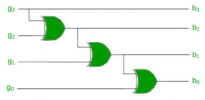
👁 Imageg0 = b0b1′ + b1b0′ = b0 ⊕ b1
g1 = b2b1′ + b1b2′ = b1 ⊕ b2
g2 = b2b3′ + b3b2′ = b2 ⊕ b3
g3 = b3
👁 ImageBoolean expression for conversion of binary to gray code for n-bit :
gn = bn
gn-1 = bn XOR bn-1 : :
g1 = b2 XOR b1
Converting gray code back to binary can be done in a similar manner. Let b0, b1, b2 and b3 be the bits representing the binary numbers, where b0 is the LSB and b3 is the MSB, and Let g0, g1, g2, and g3 be the bits representing the gray code of the binary numbers, where g0 is the LSB and g3 is the MSB.
Truth table:
| Gray Code (G3 G2 G1 G0) | Binary (B3 B2 B1 B0) |
|---|---|
| 0000 | 0000 |
| 0001 | 0001 |
| 0011 | 0010 |
| 0010 | 0011 |
| 0110 | 0100 |
| 0111 | 0101 |
| 0101 | 0110 |
| 0100 | 0111 |
| 1100 | 1000 |
| 1101 | 1001 |
| 1111 | 1010 |
| 1110 | 1011 |
| 1010 | 1100 |
| 1011 | 1101 |
| 1001 | 1110 |
| 1000 | 1111 |
Using K-map to get back the binary bits from the gray code.
K-map for b0:
👁 ImageK-map for b1:
👁 ImageK-map for b2:
👁 ImageK-map for b3:
👁 Imageb3 = g3
b2 = g3 ⊕ g2
b1 = g2 ⊕ g1
b0 = g1 ⊕ g0
Boolean expression for conversion of gray to binary code for n-bit :
bn = gn
bn-1 = bn XOR gn-1 = gn XOR gn-1 : :
b1 = b2 XOR g1 = gn XOR ............ XOR g1
Given Below are the Applications of the Code Converters - Binary to/from Gray Code