 |
VOOZH | about |
|
VOOZH | about |
In this article, we are going to learn how a sequential binary multiplier works with examples. So for that, we also need to learn a few concepts related to the sequential circuit, binary multipliers, etc. Finally solving the examples using a sequential binary multiplier method.
A sequential circuit is a combinational circuit with memory. The output of the sequential circuit depends on present inputs and present state [past outputs]. The information stored in the sequential circuit represents the present state. The present state and present input will define the output of the next state.
A binary multiplier is used to multiply two binary numbers. It is a basic electronic circuit in digital electronics, such as a computer. The binary multiplier is also called an add-shift adder.
A digital multiplier can be implemented using a variety of computer arithmetic techniques. The majority of techniques involve computing a set of partial products, which are then summed using binary adders.
Adder: An adder, also known as summer, is a digital circuit that performs number addition. Adders are used in the arithmetic logic units of many computers and other types of processors (ALUs).
Before going to sequential binary multiplication first let's see how normal binary multiplication works:
Consider two binary numbers num1 and num2
num1=12 ⇢ which equivalent to binary value as 1100 ⇢ multiplier
num2=13 ⇢ which equivalent to binary value as 1101 ⇢ multiplicand
Example 1:
 1 1 0 0
 x 1 1 0 1
----------------------
 1 1 0 0
 0 0 0 0
 1 1 0 0
1 1 0 0
--------------------
 1 0 0 1 1 1 0 0
The above multiplication is performed by a sequential binary multiplier as below:
Operation:
Consider two binary numbers num1 and num2
Step 1:
num1=12 ⇢ which equivalent to a binary value as 1100
num2=13 ⇢ which equivalent to binary value as 1101
Assume multiplier as M and multiplicand as Q
Step 2:
Here we also need the other two parameters accumulator and carry and
initially the values of both accumulator and carry will be zero.
Let,
Accumulator a = 0000
Carry c = 0
Step 3:
Q = 1 1 0 1
 q3 q2 q1 q0
if q0=0 then perform an only right shift operation
if q0=1 then perform add (A+M) and right shift operation
Here we have to perform up to 4 steps because the number of bits in the multiplier is 4
| Steps | M (Multiplier) | C (Carry) | A(Accumulator) | Q (Multiplicand) | Operation |
|---|---|---|---|---|---|
| 1100 | 0 | 0000 | 1 1 0 1 q3q2q1q0 | initialization q0=1 then perform the next step as add and shift right operation | |
| Step 1 | 1100 | 0 | 0000+ 1100 ------ 1100 0110 | 1101 0 1 1 0 q3q2q1q0 | A+M right shift operation of carry, accumulator, and quotient and discard last value i.e. q0 after shifting q0=0 perform next step only right shift operation |
| Step 2 | 1100 | 0 | 0110 0011 | 0110 0011 | right shift operation q0=1 perform next step add (A+M) and shift right operation |
| Step 3 | 1100 | 0 | 0011 1100 ------- 1111 0111 | 0011 1001 | A+M right shift operation of carry, accumulator, and quotient and discard last value i.e. q0 after shifting q0=1 perform add (A+M) and shift right operation |
| Step 4 | 1100 | 1 ---- | 0111 1100 ------- 0011 ------ 1001 | 1001 -------- 1100 | A+M right shift operation of carry, accumulator, and quotient and discard last value i.e. q0 after shifting Here is the final result of multiplication because we have to perform only 4 steps as number bits is 4 in multiplier |
Step 4:
Result = Combination of accumulator value(A) and Q =>10011100
the equivalent value is 156 obtained from the formula
.........+23+22+21+201 0 0 1 1 1 0 027+0+0+24+23+22+0+0 =156
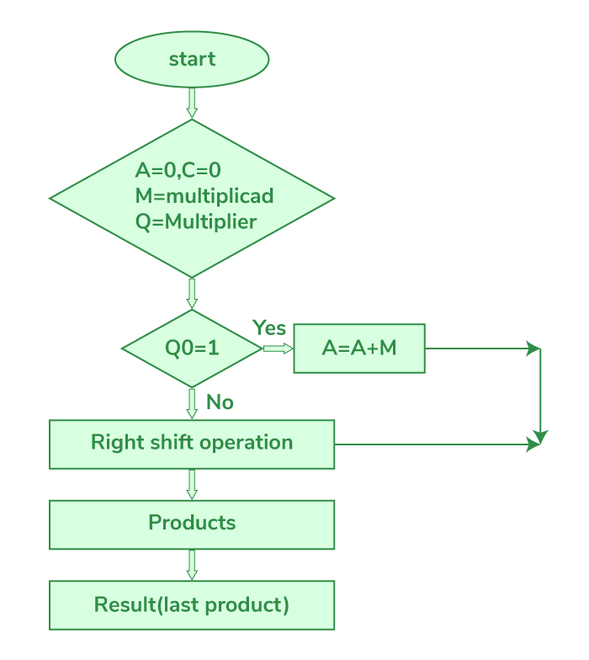
The flow chart explains the whole operation of the sequential binary multiplier in a simple manner. First, assign 0 to the accumulator and carry values. then check the LSB of Q i.e., Q0, if q0 is 0 then perform only the right shift operation and if q0 is 1 then perform the addition of the accumulator and multiplicand, store the result in the accumulator then perform the right shift operation. We have to continue this process based on the number of bits in the multiplier.
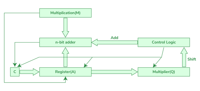
The below diagram describes the hardware circuit of the sequential binary multiplier.
Example 2: Here we have to perform up to 4 steps because the number of bits in the multiplier is 4.
| Steps | M (Multiplier) | C (Carry) | A(Accumulator) | Q (Multiplicand) | Operation |
|---|---|---|---|---|---|
| 0110 | 0 | 0000 | 1 1 1 0 q3q2q1q0 | initialization q0=0 perform next step only right shift operation | |
| Step1 | 0 | 0000 | 0111 | q0=1 then perform the next step as add and shift right operation | |
| Step2 | 0110 | 0 0 | 0000+ 0110 ------- 0110 0011 | 0111 0011 | A+M right shift operation of, accumulator and quotient and discard last value i.e. q0 after shifting q0=1 then perform the next step as add and shift right operation |
| Step3 | 0110 | 0 0 | 0011 0110 ------ 1001 0100 | 0011 1001 | A+M right shift operation of carry, accumulator, and quotient and discard last value i.e. q0 after shifting q0=1 then perform the next step as add and shift right operation |
| Step4 | 0110 | 0 0 | 0100 0110 ------ 1010 0101 | 1001 0100 | A+M right shift operation of carry, accumulator, and quotient and discard last value i.e. q0 after shifting Here is the final result of multiplication because we have to perform only 4 steps as number bits are 4 in multiplier |
Result:
Combination of accumulator value(A) and Q =>01010100
the equivalent value is 84 obtained from the formula
.........+23+22+21+200 1 0 1 0 1 0 0 0+64+0+16+0+8+0+0 ⇢ 84
Another procedure involved in binary multiplication when using a sequential binary multiplier is the right shift procedure; it is useful in the correct alignment of the binary numbers to allow subsequent operations. Here’s how the right shift operation is carried out and what it means in this context:
Since, we are dealing with unsigned binary numbers in the case of sequential binary multipliers, we generally perform a logical shift.
Initial Setup: In multiplication you have two major components involved.
To explain it methodically, let’s go through the step by step example, of a 4-bit sequence binary multiplier.
Initial Values:
1. Before Shift:
Exercise the operation on the LSB of Q (Q0). If Q0 is 1, add (A + M), or (A + 0M depending on the proper treatment of the final carry during addition) to the accumulator and then shift.
This is done for the number of bits in the multiplier, thus, the number of bits in the product will be determined by the number of times this operation is done. In which for each bit in the multiplier, if the current is equal to one, performs the addition and store it in the accumulator along with shifting right.
Sequential binary multipliers are important building blocks for the digital arithmetic and can be regarded as efficient solution for binary multiplication used in various digital circuits. Their design is anchored on simple operations such as addition and shifting and therefore easy to master. Nevertheless, their factored structure makes them slower than advanced parallel multipliers due to their sequential operation. Nevertheless, due to their simplicity and fewer demands towards the hardware these nets might be applied in number of ways, particularly in conditions when the amount of resources is limited.