 |
VOOZH | about |
|
VOOZH | about |
The acronym PWM denotes Pulse Width Modulation. By altering the width of an electrical signal's pulses, a technique used in electrical and electronic engineering can regulate the amount of power supplied to a system or device. This is frequently utilized in applications including dimming LEDs, managing the electricity supplied to heaters and other appliances, and managing the speed of motors.
Different widths of square-wave pulses are produced using PWM. The magnitude of the input signal usually correlates with the pulse width, alternatively referred to as pulse width offset. PWM is used to power LEDs or regulate motors. PWM is mostly used because it makes it possible to regulate the average power supplied to an output or load. They are also employed in communications for modulation and voltage regulation.
PWM stands for Pulse Width Modulation. It's a method used to control the analogue circuits using digital signals. In PWM, the duration of the pulse (known as the pulse width) is modulated to encode a specific analogue signal level. With pulse width modulation (PWM), the duty cycle of the pulse signal is changed to alter the average power delivered to the load. The ratio of the pulse width (on time) to the signal's overall period is known as the duty cycle. You can effectively manage the amount of power given to the load by varying the duty cycle.
The PWM period, which is the reciprocal of the pulse frequency, the pulse width offset, and the pulse delay time are often among the various tuning parameters of a PWM system. The difference in time from the pulse beginning at 0 s is represented by the pulse delay time. The values may be expressed in seconds or as a % of the PWM duration. The proportion of the PWM time T is represented by the pulse width offset . Offset is occasionally also stated in seconds. PWM signal output
The digital outputs of a microcontroller can be used to effectively control analog circuits through the use of pulse-width modulation, or PWM. PWM has a wide range of uses, from power conversion and control to communications. PWM is commonly used in various applications, such as adjusting the brightness of lights, controlling the speed of electric motors, facilitating ultrasonic cleaning processes, and serving numerous other functions.
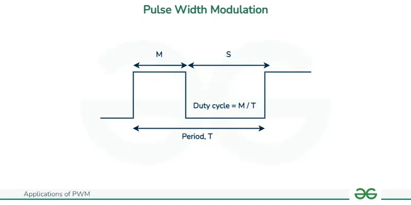
In essence, a PWM is a digital unipolar square wave signal that allows for the desired modulation (or adjustment) of the ON time length. In this manner, a microcontroller can be used to regulate the amount of power supplied to the load.
The signal's MARK (or M) and SPACE (or S) times are sometimes used to refer to the ON and OFF times, respectively. Three characteristics are of interest here: the duty cycle of the signal, its frequency (or period), and its amplitude.
Signal Generation: A microcontroller or a separate PWM generator circuit generates a periodic signal, usually a square wave, which is the first step in the PWM process.
Duty Cycle Control: Adjusting this periodic signal's duty cycle is essential to PWM.
Controlled Output: Next, a device like a motor driver, LED driver, or heating element controller receives the PWM signal.
To calculate how much power or intensity to give the load, the device analyzes the duty cycle.
A modulation technique called pulse width modulation (PWM) produces pulses with varying widths to indicate the magnitude of an analog input signal. When a signal has a large amplitude, the output switching transistor is on more of the time, and when it has a low amplitude, it is off more of the time. An analog circuit that does not drift over time is more expensive to manufacture than a PWM circuit due to its digital nature, which allows it to be fully on or off.
PWM is frequently used in ROV applications to regulate a DC motor's speed and/or a lightbulb's brightness. For instance, the target would get 50% of the voltage on average and run at if the line were closed for 1 μs, opened for 1 μs, and then repeatedly repeated.
Given Below are the Applications of PWM :
With PWM, the brightness of the screen is adjusted by turning it on and off alternately, rather than depending on power. The PWM dimming screen illuminates and turns off the screen continuously when it is on, however it does not continuously emit light. Our eyes interpret something as always on with varying brightness depending on duty cycles if it changes quickly enough. The screen gets brighter as the duty cycle increases.
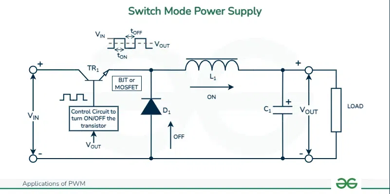
A key component of switch-mode power supplies (SMPS) is PWM. By adjusting the ON and OFF periods of the switching elements (like transistors or MOSFETs), it aids in managing the output voltage. SMPS are utilized in a wide range of electrical products, including high-power industrial applications and power adapters.
In order to keep output PWM voltage control within the necessary limits under varying load conditions, switch-mode power supplies need to incorporate a feedback control loop. This involves feeding the power supply's output voltage back via an error amplifier to produce a control signal.
PWM regulates the quantity of heat applied to a load in heating systems, which include soldering stations, electric heaters, and ovens. The average power supplied to the heating element can be precisely regulated by varying the duty cycle, providing accurate temperature control. The electrical pulse to the heater will remain on for a longer period of time the lower the setpoint feedback temperature. As a result, the heater will receive more power on average, raising the temperature until it reaches the intended setpoint.
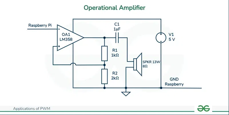
High-efficiency pulse waveforms that power speakers are created from audio signals by Class-D audio amplifiers using PWM. Portable music players employ PWM amplifiers because they are an energy-efficient option. PWM amplifiers have the primary benefit of having an exceptionally high efficiency (>90%). As a result, just 25% of the heat from prior designs needs to be dissipated, which results in substantially lower amp temperatures and eliminates the need for heat sinks.
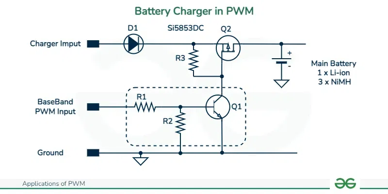
Systems that use sun charge controllers or other PWM charging controllers are used to charge batteries. To ensure that batteries are charged to the best possible degree and increase their lifespan and efficiency, they control the charging voltage and current. The best way to switch the power devices of the solar system controller and achieve consistent voltage battery charging is to use pulse width modulation, or PWM. The solar array's current tapers in accordance with the battery's state and recharging requirements when it is in PWM regulation.
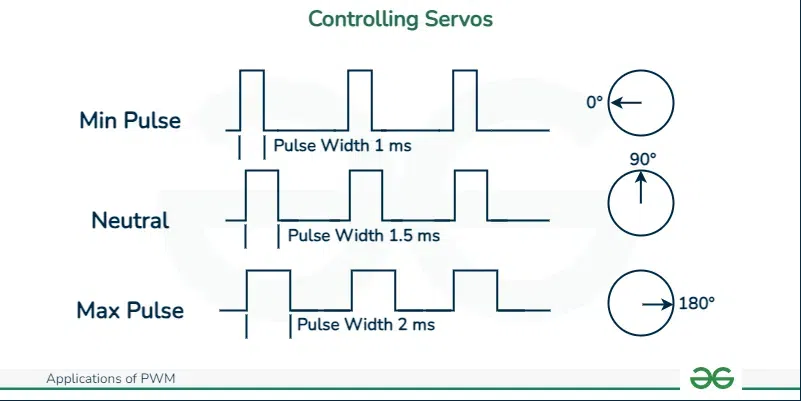
Automation systems, robotics, and RC (remote control) devices all employ PWM signals to operate servo motors. The servo motor's position is determined by the duty cycle of the PWM signal, which provides exact control over angular displacement.
A pulse width modulated (PWM) signal is used to drive servo motors. Typically, servo motors consist of three wires: the control signal, ground, and power. The majority of servos rotate fixedly in the range of 0° to 180°, beginning and finishing at fixed locations in relation to the motor.
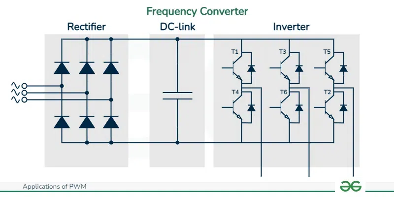
Inverters use PWM techniques to effectively convert DC power to AC power. Furthermore, PWM modifies the frequency of the output waveform in variable frequency drives (VFDs) to regulate the speed of AC motors.
This approach involves feeding the inverter a fixed dc input voltage, and controlling the on and off times of the inverter's component parts to produce a regulated ac output voltage. This technique, known as pulse-width modulation (PWM) control, is the most widely used one for adjusting the output voltage.
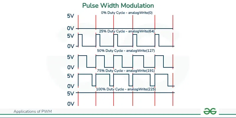
On Arduino, PWM may be done in a number of ways. Six pins on the arduino board—pins 3, 5, 6, 9, 10, and 11—can be used to output a PWM wave using the analogWrite() method. The PWM pins can produce a steady square wave with a given duty cycle by invoking the AnalogWrite() function. These pins typically have frequencies of 490 Hz, but pins 5 and 6 of Seeeduino or boards similar to it have frequencies of 980 Hz.
Arduino pins have a 5V output voltage, and as can be seen below, different duty cycles result in various voltage levels:
Duty Cycle | Output Voltage Levels |
|---|---|
0% | 0V |
25% | 1.25V |
50% | 2.5V |
75% | 3.75V |
100% | 5V |
A DC motor's speed is proportional to the power supply voltage when its load, or torque, is constant. As was previously said, the duty cycle of the PWM controls the output voltage level, meaning that the motor speed may be adjusted using the PWM.
Hardware Link
There are certain disadvantages to PWM in power electronics systems.
To sum up, pulse width modulation, or PWM, is a flexible method that can be applied to a wide range of situations to effectively control power delivery, modulate signals, and regulate systems. It makes it possible to precisely manage a variety of factors, including heating components, LED brightness, motor speed, and audio output. Due to its capacity to adjust a signal's duty cycle, PWM is a vital component of contemporary automation, power management, and electronics systems.
.webp)