 |
VOOZH | about |
|
VOOZH | about |
A microprocessor is fabricated on a single integrated circuit (IC) or chip that is used as a central processing unit (CPU).The 8085 microprocessor is an 8-bit microprocessor that was developed by Intel in the mid-1970s. It was widely used in the early days of personal computing and was a popular choice for enthusiasts due to its simplicity and ease of use. The architecture of the 8085 microprocessor consists of several key components, including the accumulator, registers, program counter, stack pointer, instruction register, flags register, data bus, address bus, and control bus.
The accumulator is an 8-bit register that is used to store arithmetic and logical results. It is the most commonly used register in the 8085 microprocessor and is used to perform arithmetic and logical operations such as addition, subtraction, and bitwise operations.
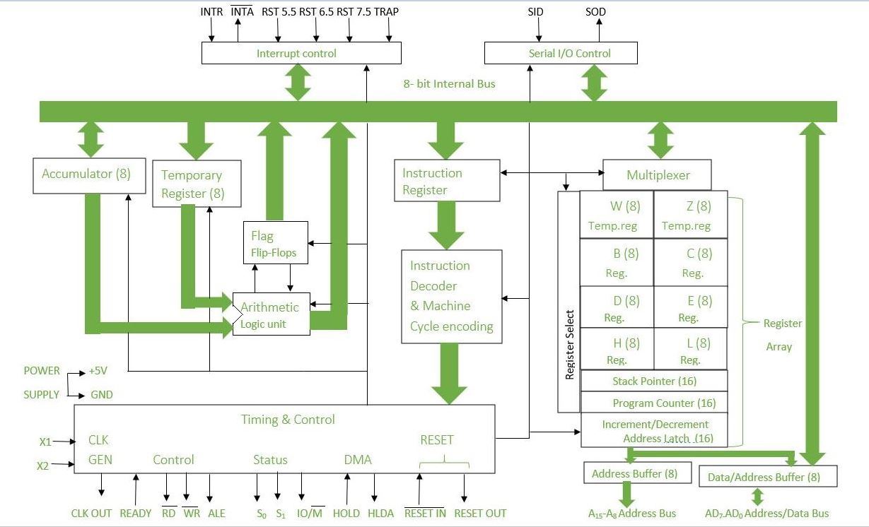
8085 is an 8-bit, general-purpose microprocessor. It consists of the following functional units:
👁 Architecture of 8085 microprocessor
It is used to perform mathematical operations like addition, multiplication, subtraction, division, decrement, increment, etc. Different operations are carried out in ALU: Logical operations, Bit-Shifting Operations, and Arithmetic Operations.
It is an 8-bit register that stores either 0 or 1 depending upon which value is stored in the accumulator. Flag Register contains 8-bit out of which 5-bits are important and the rest of 3-bits are "don't Care conditions". The flag register is a dynamic register because after each operation to check whether the result is zero, positive or negative, whether there is any overflow occurred or not, or for comparison of two 8-bit numbers carry flag is checked. So for numerous operations to check the contents of the accumulator and from that contents if we want to check the behavior of given result then we can use Flag register to verify and check. So we can say that the flag register is a status register and it is used to check the status of the current operation which is being carried out by ALU.
Accumulator is used to perform I/O, arithmetic, and logical operations. It is connected to ALU and the internal data bus. The accumulator is the heart of the microprocessor because for all arithmetic operations Accumulators' 8-bit pin will always there connected with ALU and in most-off times all the operations carried by different instructions will be stored in the accumulator after operation performance.
There are six general-purpose registers. These registers can hold 8-bit values. These 8-bit registers are B,C,D,E,H,L. These registers work as 16-bit registers when they work in pairs like B-C, D-E, and H-L. Here registers W and Z are reserved registers. We can't use these registers in arithmetic operations. It is reserved for microprocessors for internal operations like swapping two 16-bit numbers. We know that to swap two numbers we need a third variable hence here W-Z register pair works as temporary registers and we can swap two 16-bit numbers using this pair.
Program Counter holds the address value of the memory to the next instruction that is to be executed. It is a 16-bit register.
For Example: Suppose current value of Program Counter : [PC] = 4000H
(It means that next executing instruction is at location 4000H.After fetching,program Counter(PC) always increments
by +1 for fetching of next instruction.)
It works like a stack. In stack, the content of the register is stored that is later used in the program. It is a 16-bit special register. The stack pointer is part of memory but it is part of Stack operations, unlike random memory access. Stack pointer works in a continuous and contiguous part of the memory. whereas Program Counter(PC) works in random memory locations. This pointer is very useful in stack-related operations like PUSH, POP, and nested CALL requests initiated by Microprocessor. It reserves the address of the most recent stack entry.
It is an 8-bit register that holds data values during arithmetic and logical operations.
It is an 8-bit register that holds the instruction code that is being decoded. The instruction is fetched from the memory.
The timing and control unit comes under the CPU section, and it controls the flow of data from the CPU to other devices. It is also used to control the operations performed by the microprocessor and the devices connected to it. There are certain timing and control signals like Control signals, DMA Signals, RESET signals and Status signals.
Whenever a microprocessor is executing the main program and if suddenly an interrupt occurs, the microprocessor shifts the control from the main program to process the incoming request. After the request is completed, the control goes back to the main program. There are 5 interrupt signals in 8085 microprocessors: INTR, TRAP, RST 7.5, RST 6.5, and RST 5.5.
Priorities of Interrupts: TRAP > RST 7.5 > RST 6.5 > RST 5.5 > INTR
The data bus is bidirectional and carries the data which is to be stored. The address bus is unidirectional and carries the location where data is to be stored.
In the 8085 microprocessor, the address bus and data bus are two separate buses that are used for communication between the microprocessor and external devices.
The Address bus is used to transfer the memory address of the data that needs to be read or written. The address bus is a 16-bit bus, allowing the 8085 to access up to 65,536 memory locations.
The Data bus is used to transfer data between the microprocessor and external devices such as memory and I/O devices. The data bus is an 8-bit bus, allowing the 8085 to transfer 8-bit data at a time. The data bus can also be used for instruction fetch operations, where the microprocessor fetches the instruction code from memory and decodes it.
The combination of the address bus and data bus allows the 8085 to communicate with and control external devices, allowing it to execute its program and perform various operations.
It controls the serial data communication by using Serial input data and Serial output data.
Serial Input/Output control in the 8085 microprocessor refers to the communication of data between the microprocessor and external devices in a serial manner, i.e., one bit at a time. The 8085 has a serial I/O port (SID/SOD) for serial communication. The SID pin is used for serial input and the SOD pin is used for serial output. The timing and control of serial communication is managed by the 8085's internal circuitry. The 8085 also has two special purpose registers, the Serial Control Register (SC) and the Serial Shift Register (SS), which are used to control and monitor the serial communication.
The 8085 microprocessor is a versatile 8-bit microprocessor that has been used in a wide variety of applications, including:
Here are some common issues with the 8085 microprocessor: