 |
VOOZH | about |
|
VOOZH | about |
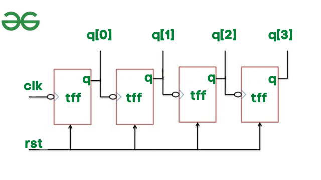
To proceed with Verilog Code, we shall first understand the structure of the 4-bit Ripple Counter. The top design block consists of four T-Flip Flop. For time being ignore the input and output of T-Flip Flop. Let us consider the overall outside structure of Ripple Counter. We have two inputs i.e., clock and reset and q is output. The output q is in 4-bit vector form.
In Ripple Carry Counter, first, the clock signal is passed through the first T Flip Flop. For the second T Flip Flop, the output of the first T Flip Flop acts as a clock and so on. The reset is the same for all the T flip flops.
Let us now implement the ripplecounter block.
module ripplecounter(clk,rst,q);
 input clk,rst;
 output [3:0]q;

 // initiate 4 T-FF to update the count
 tff tf1(q[0],clk,rst);
 tff tf2(q[1],q[0],rst);
 tff tf3(q[2],q[1],rst);
 tff tf4(q[3],q[2],rst);
endmodule
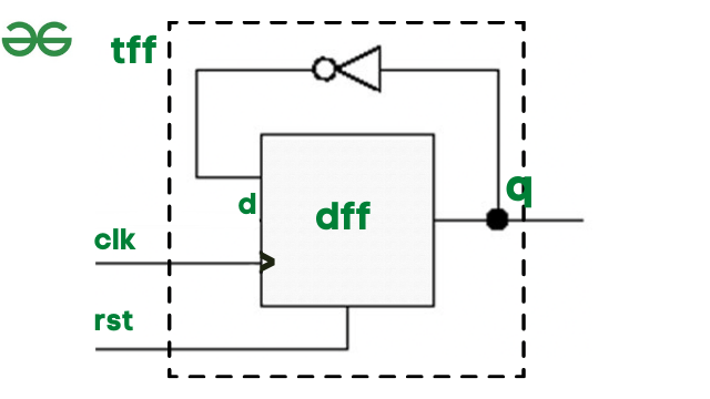
Since we instantiated tff in ripplecounter, now let's see the inner of T Flip Flop. Inside T- Flip flop we have a D flip flop and an inverter i.e., not a gate. To implement T- Flip flop we need to instantiate d flip and flop, and we have clk and reset as input and q as output. We need an additional wire d, which further acts as input for the D-flip flop.
module tff(q,clk,rst);
 // tff takes clk and reset as input
 // q is output
 input clk,rst;
 output q;
 wire d;
 // by referring the diagram of tff,
 // instantiate d flip flop and not gate
 dff df1(q,d,clk,rst);
 not n1(d,q);
endmodule
D Flip Flop Truth Table for Reference:
| clk | rst | d | q |
|---|---|---|---|
| ⇡ | 1 | x | 0 |
| ⇡ | 0 | 0 | 0 |
| ⇡ | 0 | 1 | 1 |
module ripplecounter(clk,rst,q);
 input clk,rst;
 output [3:0]q;

 // initiate 4 T-FF to update the count
 tff tf1(q[0],clk,rst);
 tff tf2(q[1],q[0],rst);
 tff tf3(q[2],q[1],rst);
 tff tf4(q[3],q[2],rst);
endmodule

module tff(q,clk,rst);
 // tff takes clk and reset as input
 // q is output
 input clk,rst;
 output q;
 wire d;
 // by referring the diagram of tff,
 // instantiate d flip flop and not gate
 dff df1(q,d,clk,rst);
 not n1(d,q);
endmodule

module dff(q,d,clk,rst);
 input d,clk,rst;
 output q;
 reg q; // store the output value
 always @(posedge clk or posedge rst)
 begin
 // refer the truth table to provide
 // values to q based on reset.
 if(rst) q=1'b0;
 else q=d;
 endripplecounter
endmodule
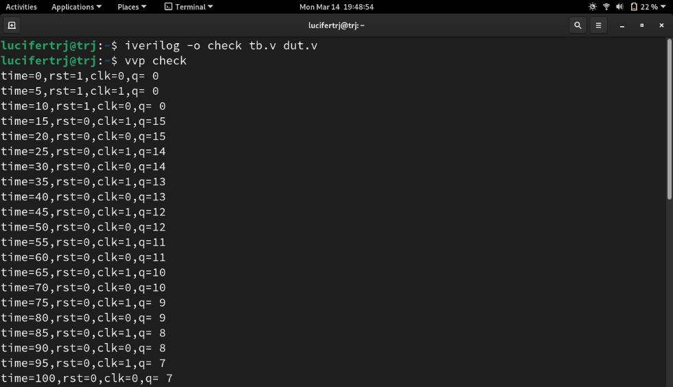
Simulation is used to verify the design block by providing the input values to the dut. We need to write testbench with reference to ripplecounter block, where we have clk and reset as the input.
The clock needs to toggle after a specific time unit, thus we initially provide clk as 0. And then after every 5-time unit, we toggle the clock from 0 to 1 and vice versa under always block.
initial
 clk=0;
always
 #5 clk=~clk;
Here is the simulation of the ripplecounter:
module tb;
 // input to be stored in reg and output as net(wire)
 reg clk;
 reg rst;
 wire [3:0]q;

 // instantiate the ripplecounter design block
 ripplecounter dut(clk,rst,q);

 // generate clock pulse
 // initially provide 0
 // then inside always block toggle
 // clock every 5 time units
 initial
 clk = 0;
 always
 #5 clk = ~clk;

 // provide reset values as the input
 initial
 begin
 rst = 1;
 #15 rst = 0;
 #180 rst = 1;
 #10 rst = 1;
 #20 $finish;
 end
 initial
 $monitor("time=%g,rst=%b,clk=%b,q=%d",$time,rst,clk,q);
endmoduleAs it can be seen when reset is 0, the output q has the counter output updates, and the count.