 |
VOOZH | about |
|
VOOZH | about |
Combinational circuits are digital circuits. In these circuits output is determined by the current input values. The current output is not dependent on any memory or feedback from previous results. There are various functions performed by Combinational Circuits. Example include logic operations, arithmetic operations, data routing etc.
In this article we are going to learn how to construct any type of combinational circuit using general steps.
Following are the general steps for constructing a combinational circuit:
The first step in constructing a combinational circuit is to carefully analyze the given problem. This involves identifying the inputs and outputs of the circuit. Inputs can be binary values (0 or 1), and outputs are the result of processing these inputs through logical operations. It is important to define the number of input variables and the expected output variables before moving to the next steps.
Once the inputs and outputs are defined, the next step is to create a truth table. The truth table lists all possible combinations of input values and the corresponding output values. For 'n' inputs, there will be 2n possible input combinations. This table serves as the foundation for deriving the logic that will define the behavior of the combinational circuit.
With the truth table in hand, the next step is to derive the Boolean expression for the circuit. This can be done by using the Sum of Products (SOP) or Product of Sums (POS) forms, depending on the circuit's logic requirements. In SOP, each row of the truth table where the output is 1 is written as a product (AND) of the input variables. In POS, the process is reversed, where rows with output 0 are written as sums (OR) of the input variables.
After deriving the initial Boolean expression, the next step is simplification. The Boolean expression can be simplified using techniques like Karnaugh Maps (K-map) or algebraic methods. K-maps help to minimize the number of terms in the Boolean expression, leading to a more efficient circuit design with fewer gates and components. Simplification is critical for reducing the complexity and improving the performance of the circuit.
The final step is to implement the simplified Boolean expression into a logic diagram. This involves translating the simplified Boolean expression into a schematic using basic logic gates (AND, OR, NOT, etc.). The logic diagram visually represents how the inputs are processed to produce the desired output, and it serves as the blueprint for physical circuit implementation.
A 3-to-8 decoder is a combinational circuit that takes 3 binary inputs and decodes them into one of 8 output lines. This means that out of 8 output lines, only one will be activated based on the binary input values, and all other outputs will remain inactive.
The truth table for a 3-to-8 decoder maps all possible combinations of inputs to their corresponding output lines. Here, there are 8 possible input combinations for 3 inputs (since 23 = 8).
A | B | C | Y0 | Y1 | Y2 | Y3 | Y4 | Y5 | Y6 | Y7 |
|---|---|---|---|---|---|---|---|---|---|---|
0 | 0 | 0 | 1 | 0 | 0 | 0 | 0 | 0 | 0 | 0 |
0 | 0 | 1 | 0 | 1 | 0 | 0 | 0 | 0 | 0 | 0 |
0 | 1 | 0 | 0 | 0 | 1 | 0 | 0 | 0 | 0 | 0 |
0 | 1 | 1 | 0 | 0 | 0 | 1 | 0 | 0 | 0 | 0 |
1 | 0 | 0 | 0 | 0 | 0 | 0 | 1 | 0 | 0 | 0 |
1 | 0 | 1 | 0 | 0 | 0 | 0 | 0 | 1 | 0 | 0 |
1 | 1 | 0 | 0 | 0 | 0 | 0 | 0 | 0 | 1 | 0 |
1 | 1 | 1 | 0 | 0 | 0 | 0 | 0 | 0 | 0 | 1 |
In the truth table above, for each combination of inputs, only one output is high (1), and all others are low (0).
For each output, we write the Boolean expression based on when it is high.
For example:
Y0 = A'.B'.C'
Y1 = A'.B'.C
Y2 = A'.B.C'
Similarly, for the other outputs, we can write the Boolean expressions based on their respective input combinations.
For a 3-to-8 decoder, the Boolean expressions for each output are already simplified, as each output is uniquely determined by one specific combination of inputs. The Boolean expressions are:
Y0 = A'.B'.C'
Y1 = A'.B'.C
Y2 = A'.B.C'
Y3 = A'.B.C
Y4 = A.B'.C'
Y5 = A.B'.C
Y6 = A.B.C'
Y7 = A.B.C
Each output expression is already in its simplest form, so there is no need for further simplification using methods like K-map.
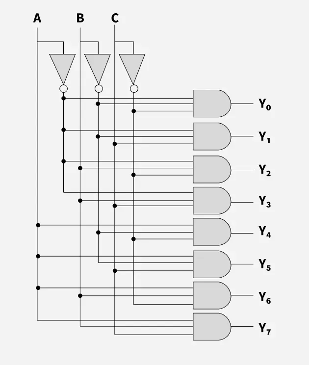
Now that we have the Boolean expressions for each output, we can implement the logic diagram using basic logic gates:
The circuit consists of:
The logic diagram will look like this: