 |
VOOZH | about |
|
VOOZH | about |
Flip Flop is popularly known as the basic digital memory circuit. It has two states as logic 1(High) and logic 0(low) states. A flip flop is a sequential circuit which consists of a single binary state of information or data. The digital circuit is a flip flop which has two outputs and are of opposite states. It is also known as a Bistable Multivibrator.
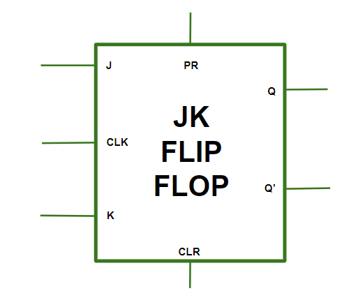
The JK flip-flop is the form of sequential circuits which are applied as the basic elements of the digital memory. It is known to be flexible and is applied in different systems in the digital platform. This JK flip-flop has two input lines J and K, clock line CLK, clear line CLR as well as preset line PR. Q and Q’ are its two output which are usually in the opposite state while operating. The JK flip-flop can also be called a bistable multivibrator since it has two stable steady states.
The JK flip flop diagram below represents the basic structure which consists of Clock (CLK), Clear (CLR), and Preset (PR).
👁 ImageThis condition is in its invalid state.PR = CLR = 0
The PR is activated which means the output in the Q is set to 1. Therefore, the flip flop is in the set state.PR = 0 and CLR = 1
The CLR is activated which means the output in the Q’ is set to 1. Therefore, the flip flop is in the reset state.PR = 1 and CLR = 0
In this condition, the flip flop works in its normal way whereas the PR and CLR gets deactivated.PR = CLR = 1
Inputs | Outputs | Comments | ||||||||||
|---|---|---|---|---|---|---|---|---|---|---|---|---|
PR | CLR | CLK | J | K | Q(n+1) | Q'(n+1) | ||||||
0 | 1 | NA | NA | NA | 1 | 0 | Set (Preset) | |||||
1 | 0 | NA | NA | NA | 0 | 1 | Reset (Clear) | |||||
1 | 1 | 0 | NA | NA | Q(n) | Q'(n) | Initial Stage | |||||
1 | 1 | 1 | 0 | 0 | Q(n) | Q'(n) | Initial Stage | |||||
1 | 1 | 1 | 1 | 0 | 1 | 0 | Set | |||||
1 | 1 | 1 | 0 | 1 | 0 | 1 | Reset | |||||
1 | 1 | 1 | 1 | 1 | Q'(n) | Q(n) | Toggle | |||||
Race Around Condition in JK Flip-Flop
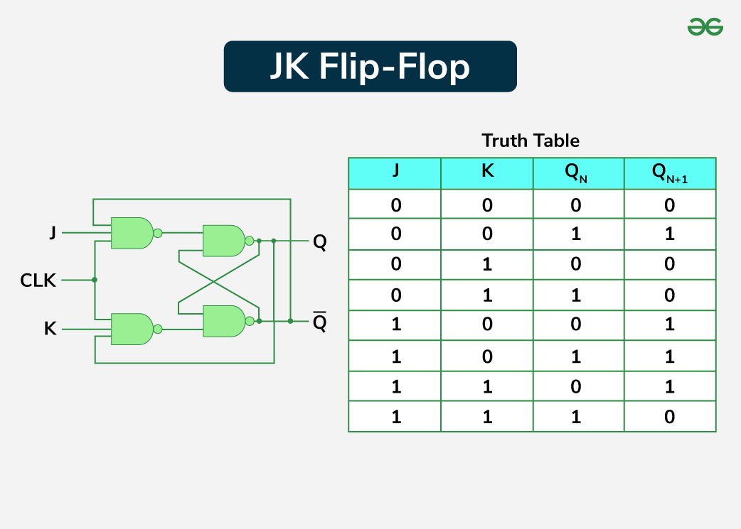
When the J and K both are set to 1, the input remains high for a longer duration of time, then the output keeps on toggling. Toggle means switching in the output instantly i.e. Q = 0, Q’ = 1 will immediately change to Q = 1 and Q’ = 0 and this continuation keeps on changing. This change in output leads to Race Around Condition.
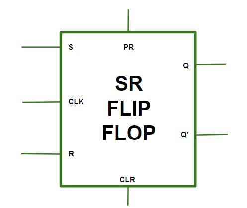
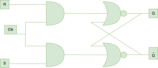
The SR flip-flop or the Set-Reset flip-flop is one of the primary building blocks of digital circuits used to store binary data. It has two inputs for data Set (S) and Reset (R); while for preset (PR) and clear (CLR) they are asynchronous. The SR flip-flop has two output signals Q and Q’ which are the opposite of each other. It is employed for holding one bit of information and it can be established or cleared depending on the signals. The SR flip-flop is used commonly in numerous digital circuits in addition to applications in which simple binary storage is required.
In SR flip flop, with the help of Preset and Clear, when the power is switched ON, the state of the circuit keeps on changing, i.e. it is uncertain. It may come to Set (Q = 1) or Reset (Q’ = 0) state. In many applications, it is desired to initially Set or Reset the flip flop. This thing is accomplished by the Preset (PR) and the Clear (CLR).
👁 ImageThe asynchronous inputs are inactive and the flip flop responds freely to the S, R and the CLK inputs in the normal way.PR = CLR = 1
This is used when the Q is set to 1.PR = 0 and CLR = 1
This is used when the Q’ is set to 1.PR = 1 and CLR = 0
This is an invalid state.PR = CLR = 0
Inputs | Outputs | Comments | ||||||||||
|---|---|---|---|---|---|---|---|---|---|---|---|---|
PR | CLR | CLK | S | R | Q(n+1) | Q'(n+1) | ||||||
0 | 1 | NA | NA | NA | 1 | 0 | Set | |||||
1 | 0 | NA | NA | NA | 0 | 1 | Reset | |||||
1 | 1 | 0 | NA | NA | Q(n) | Q'(n) | No change | |||||
1 | 1 | 1 | 0 | 0 | Q(n) | Q'(n) | No change | |||||
1 | 1 | 1 | 1 | 0 | 1 | 0 | Set | |||||
1 | 1 | 1 | 0 | 1 | 0 | 1 | Reset | |||||
1 | 1 | 1 | 1 | 1 | NA | NA | Not allowed | |||||
Parameter | JK Flip-Flop | SR Flip-Flop |
|---|---|---|
Input | Has two inputs J & K. | It is a sequential circuit that has two inputs namely Set (S) and Reset (R). |
Toggling | When the J and K inputs are high then the JK flip-flop changes its present state or status. | When both inputs S & R are high the SR flip-flop is in said to be in an invalid state. |
Race Condition | May develop a race-around condition especially where parameter J is equal to 1 and K is also equal to 1. | There is no race-around condition while the undefined matrix is at the state where S = 1 and R = 1. |
Usage | More versatile and can perform the functions of an SR flip-flop in addition to other useful functions and do not possess the invalid state. | Less complex in the design but not as flexible because of the existence of the invalid state. |
Complexity | Slightly more complicated in design due to the other gates that enable toggling condition and therefore takes a little more effort to produce. | Smaller in size in terms of the number of gates used in it implementation hence easily implementable in fundamental circuits. |
This article was useful in that it gave general information on the operation of JK and SR flip-flops as well as their strengths and weaknesses I addition to a comparison of the two. It is critical to know such behaviors of flip-flops in order to employ them and control digital memory circuits in numerous applications.