 |
VOOZH | about |
|
VOOZH | about |
Logic circuits can be combinational or sequential. A combinational circuit consists of logic gates whose outputs at any time are determined from only the present combination of inputs. The operation of combinational circuits can be specified logically by a set of Boolean functions.
Sequential circuits contain storage elements in addition to logic gates. The outputs of sequential circuits are a function of the inputs and the state of the storage elements.
As the state of the storage elements is a function of previous inputs, the output of a sequential circuit depend not only on present values of inputs, but also on past inputs. The circuit behavior must be specified by a time sequence of inputs and internal states.
A combinational circuit consists of an interconnection of logic gates. Combinational circuits react to the values at their inputs and produce the value of the output signal, transforming binary in formation from the given input data to a required output data.
To design the combinational circuits, the procedure involves the following steps:
To obtain the output Boolean functions from a logic diagram, we do:
To obtain the truth table directly from the logic diagram, steps are below:
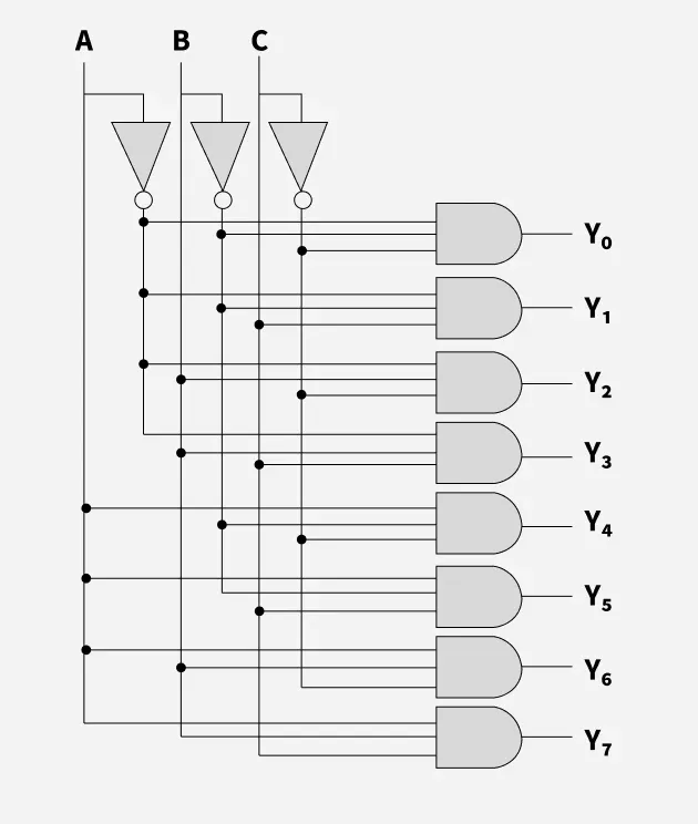
Let's take an example of 3 Line to 8 Line Decoder:
Truth Table:
| A | B | C | Y0 | Y1 | Y2 | Y3 | Y4 | Y5 | Y6 | Y7 |
|---|---|---|---|---|---|---|---|---|---|---|
| 0 | 0 | 0 | 1 | 0 | 0 | 0 | 0 | 0 | 0 | 0 |
| 0 | 0 | 1 | 0 | 1 | 0 | 0 | 0 | 0 | 0 | 0 |
| 0 | 1 | 0 | 0 | 0 | 1 | 0 | 0 | 0 | 0 | 0 |
| 0 | 1 | 1 | 0 | 0 | 0 | 1 | 0 | 0 | 0 | 0 |
| 1 | 0 | 0 | 0 | 0 | 0 | 0 | 1 | 0 | 0 | 0 |
| 1 | 0 | 1 | 0 | 0 | 0 | 0 | 0 | 1 | 0 | 0 |
| 1 | 1 | 0 | 0 | 0 | 0 | 0 | 0 | 0 | 1 | 0 |
| 1 | 1 | 1 | 0 | 0 | 0 | 0 | 0 | 0 | 0 | 1 |
If you need to design a system that stores and uses previous input and output, then we can not use a combinational circuit because it doesn't have capability to store any state or depend clock or and time. For these properties you can use Sequential circuits.
Sequential circuits are logic circuits with memory. The output depends on current inputs and the past (i.e., previous state). They are digital circuits that store and use previous state information to determine their next state. They are commonly used in digital systems to implement state machines, timers, counters, and memory elements and are essential components in digital systems design
Types of Sequential Circuits:
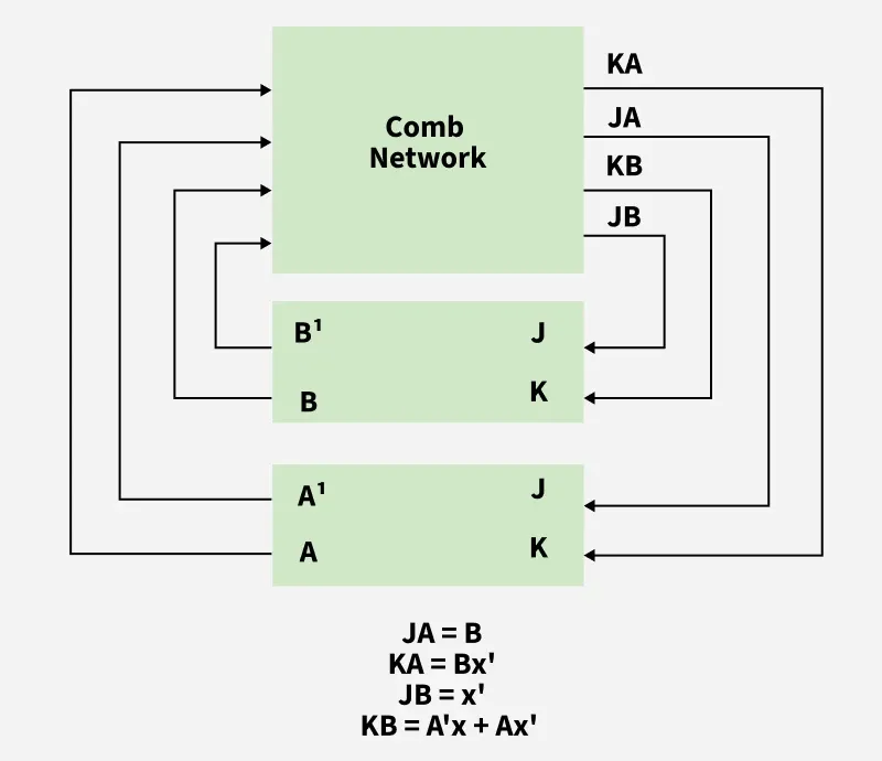
JA=B
KA=Bx'
JB=x'
KB=A' x +A x'
Step 1: Construct the truth table of the combinational network.
X | A | B | JA | KA | JB | KB |
|---|---|---|---|---|---|---|
0 | 0 | 0 | 0 | 0 | 1 | 0 |
0 | 0 | 1 | 1 | 1 | 1 | 0 |
0 | 1 | 0 | 0 | 0 | 1 | 1 |
0 | 1 | 1 | 1 | 1 | 1 | 1 |
1 | 0 | 0 | 0 | 0 | 0 | 1 |
1 | 0 | 1 | 1 | 0 | 0 | 1 |
1 | 1 | 0 | 0 | 0 | 0 | 0 |
1 | 1 | 1 | 1 | 0 | 0 | 0 |
Step 2: Find A(t+1) and B(t+1), with the help of a characteristic table.
The characteristic table of a JK flip-flop,
J K | Q(t+1) | action |
|---|---|---|
0 0 | Q(t) | no change |
0 1 | 0 | reset |
1 0 | 1 | set |
1 1 | Q'(t) | compliment |
Step 3: Final Table.
X | A | B | JA | KA | JB | KB | A(t+1) | B(t+1) |
|---|---|---|---|---|---|---|---|---|
0 | 0 | 0 | 0 | 0 | 1 | 0 | 0 | 1 |
0 | 0 | 1 | 1 | 1 | 1 | 0 | 1 | 1 |
0 | 1 | 0 | 0 | 0 | 1 | 1 | 1 | 1 |
0 | 1 | 1 | 1 | 1 | 1 | 1 | 0 | 0 |
1 | 0 | 0 | 0 | 0 | 0 | 1 | 0 | 0 |
1 | 0 | 1 | 1 | 0 | 0 | 1 | 1 | 0 |
1 | 1 | 0 | 0 | 0 | 0 | 0 | 1 | 0 |
1 | 1 | 1 | 1 | 0 | 0 | 0 | 1 | 1 |